Overview
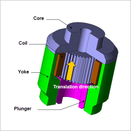
In solenoid injectors, one of the reasons for slow response is eddy currents, which are produced when the magnetic flux generated by current flow undergoes time variations. The eddy currents are generated in a direction that inhibits changes in the magnetic flux, causing a delay in the initial rise of the attraction force when the current begins to flow. This reduces the injector’s responsiveness. JMAG makes it possible to account for effects from eddy currents and obtain an injector’s responsiveness by running a transient response analysis. Identifying the places where eddy currents are generated enables a designer to study how responsiveness can be improved.
This Application Note explains how to apply direct current voltage to a solenoid injector and obtain its response characteristics by accounting for effects from eddy currents. The effectiveness of slots added to reduce eddy currents are evaluated by comparing the analysis results with a model without slots added.
Joule Loss / Current Density Distribution
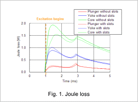
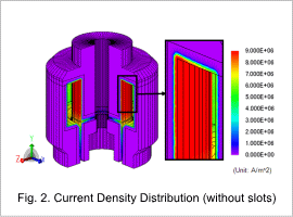
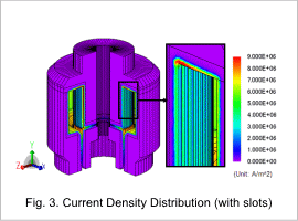
The joule loss for each part is shown in fig. 1, and current density distributions at 1.3 ms, when the core’s joule loss is at its approximate peak, are shown in figures 2 and 3.
Fig. 1 shows that the joule loss is particularly different in the core, and the peak joule loss is reduced by 20%. Eddy currents are reduced by using a core with narrow slots installed, as shown in figures 2 and 3.
Response Characteristics
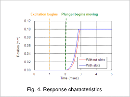
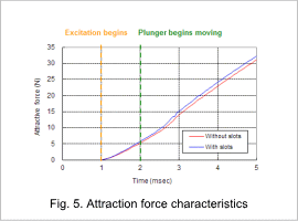
Fig. 4 shows the response characteristics, and fig. 5 shows the attraction force characteristics of the plunger versus time.
The displacement of the plunger is in the direction the valve opens, and the valve is fully open at a position of 0.1 mm. There is a constant fuel pressure of 5 N against the direction of the displacement. The plunger does not move right after the current is applied, but rather begins moving when the attraction force exceeds the fuel pressure, as indicated in the figures. The response characteristics and attraction force are improved by adding slots to reduce eddy currents.
