Overview
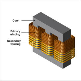
Using finite element analysis (FEA) to confirm the distribution of iron loss density makes it possible to study a transformer’s local geometry during design. Further, iron loss is divided into hysteresis loss caused by hysteresis in the core and joule loss caused by eddy currents, and analysis makes it possible to compare the relative contributions of each of these.
This Application Note presents how to obtain the iron loss and the ratio of hysteresis loss and joule loss within that iron loss for a three-phase transformer.
Magnetic Flux Density Distribution/Iron Loss Density Distribution
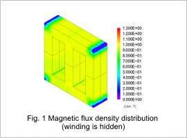
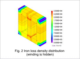
The core’s magnetic flux density distribution and iron loss density distribution are shown in figures 1 and 2, respectively. The magnetic flux density distribution and iron loss distribution are similar, as indicated in the figures. This is because the frequency of the magnetic flux density variations is constant, so the size of the iron losses is proportional to the size of the magnetic flux density variations.
Joule Loss Density Distribution/ Hysteresis Loss Density Distribution
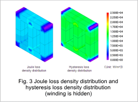
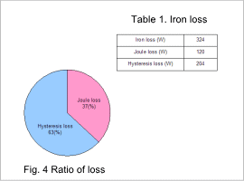
The core’s joule loss density distribution and hysteresis loss density distribution are shown in fig. 3, the ratio of losses is shown in fig. 4, and the losses are shown in table 1. As can be seen from the figures, the contribution of the hysteresis loss toward the iron loss is large. From this, it seems that investigating ways to reduce hysteresis loss would be effective in reducing iron loss.
