Overview
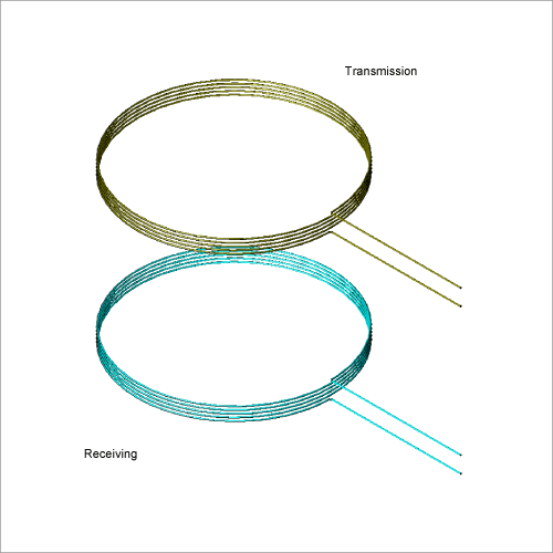
It is very difficult to use measurement to visualize how magnetic field is being generated, and is therefore transmitting power, in the space between the transmitting side and the receiving side. Reproducing the power transmission state using analysis can help with designing optimized coils.
This Application Note presents how to confirm the power transmission efficiency and the magnetic flux density distribution.
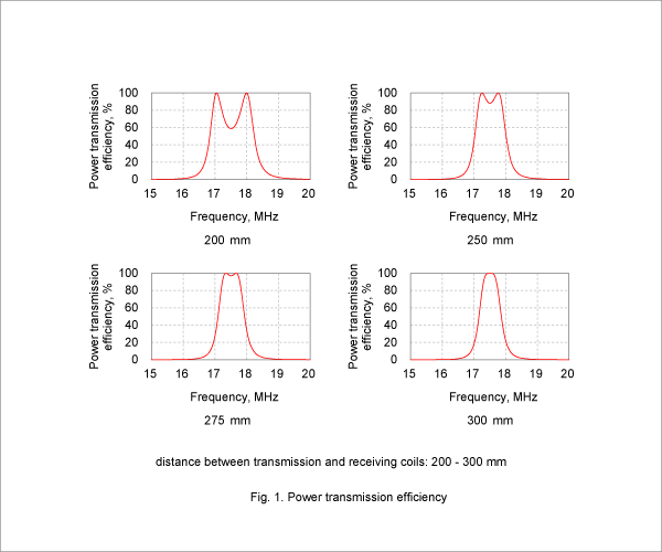
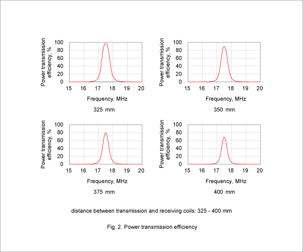
Power Transmission Efficiency
Graphs of power transmission efficiency for varying distances between the transmission and receiving coils are shown in Fig. 1 and Fig. 2.
From Fig. 1, it is apparent that with distances between the coils of 200 to 275 mm, there are peaks to each side of the resonance frequency of 17.5 MHz, at which a transmission frequency of nearly 100 % is achieved. With a distance between the coils of 300 mm, there is one consolidated peak equal to the resonance frequency.
Fig. 2 shows that with distances between the coils of 325 to 400 mm, power transmission efficiency does not reach 100 % even at its peak, meaning reduced efficiency. Therefore, it can be said that the optimal distance for power transmission at a resonance frequency of 17.5 MHz is around 300 mm.
Magnetic Flux Density Distribution
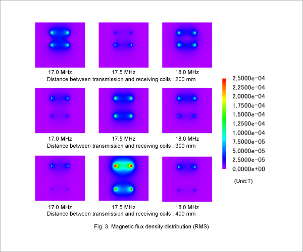
The Fig. 3 makes it clear that, for each distance between transmission and receiving coils, magnetic flux density is larger near the receiving coil at a frequency with good power transmission efficiency.

