Overview
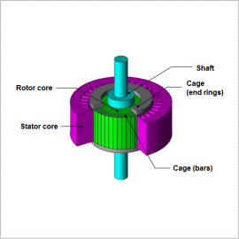
An induction motor’s characteristics are influenced by leakage reactance and resistance, including resistance on the secondary side. These are referred to as equivalent circuit parameters, and they are important because they characterize a device’s properties.
Equivalent circuit parameters are greatly affected by both the current distribution induced in the auxiliary conductor and the magnetic saturation near the gap, so a finite element analysis (FEA) needs to be run in order to investigate these characteristics with precision.
This Application Note explains how to obtain the secondary resistance, leakage inductance, and excitation inductance of an induction motor when its power supply frequency has been changed with regard to its voltage and current controls.
Equivalent Circuit Parameter Frequency Characteristics (Voltage Control)
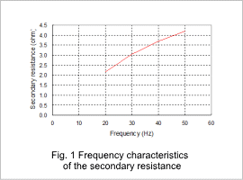
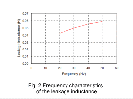
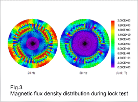
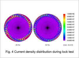
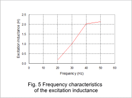
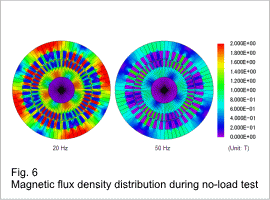
The secondary resistance when the power supply frequency in the voltage control has been changed is shown in fig. 1, the leakage inductance is shown in fig. 2, the magnetic flux density distribution during the lock test is shown in fig. 3, the current density distribution is shown in fig. 4, the excitation inductance is shown in fig. 5, and the magnetic flux density distribution during the no-load test is shown in fig. 6. The leakage inductance is the sum of the primary and secondary leakage inductances.
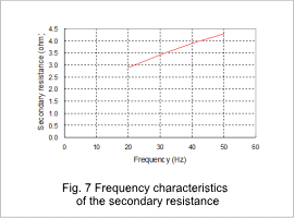
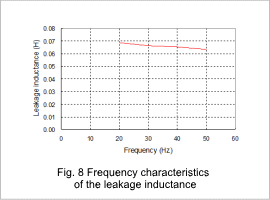
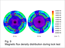
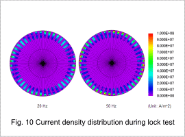
The equivalent circuit parameters change according to the frequency in each result. This is because the primary and secondary currents as well as the current distribution in the bars change according to the frequency.
Equivalent Circuit Parameter Frequency Characteristics (Current Control)
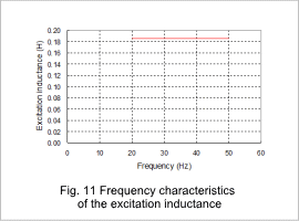
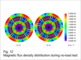
The secondary resistance when the power supply frequency in the current control has been changed is shown in fig. 7, the leakage inductance is shown in fig. 8, the magnetic flux density distribution during the lock test is shown in fig. 9, the current density distribution is shown in fig. 10, the excitation inductance is shown in fig. 11, and the magnetic flux density distribution during the no-load test is shown in fig. 12. The leakage inductance is the sum of the primary and secondary leakage inductances.
The equivalent circuit parameters change according to the frequency in each result. The excitation inductance also has a constant value. For current control, the excitation current during the no-load test does not change with the frequency and the excitation inductance is constant because induction current does not flow through the cage.
