*Please prepare a license ID and password for the license administrator.
*It is different from the service for JMAG WEB MEMBER (free membership). Please be careful.
Overview

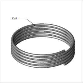
In a high frequency application, not only the coil’s inductance component but its capacitance component cannot be ignored and results in degradation of the circuit impedance characteristics and inconsistencies in resonance frequencies. Stray capacitance that occurs between the coil windings is one of them. For example, with a helical coil, electrical potential varies depending on its rotation so difference in electrical potential occurs between the neighboring windings. As a result, capacitance occurs between the windings and operates as a condenser component.
The stray capacitance that occurs in the coil depends on its geometry. To obtain the stray capacitance that occurs in various types of coils, a magnetic analysis using FEM is effective. By modeling the entire coil, stray capacitance accounting for the distance between windings and differences in winding pattern can be obtained.
This document introduces target on the helical coil, changes the distance between windings, and obtains stray capacitance that occurs in each coil.
Stray capacitance

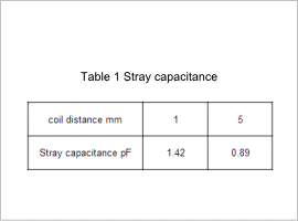
Stray capacitance obtained from the analysis results are shown in Table 1. The stray capacitance is larger when the coil distance is shorter.
Electric potential distribution, Current density distribution
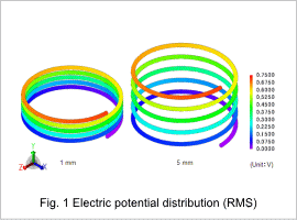
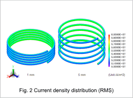
Each electric potential (intensity) distribution of when electric potential of 1(V) is supplied between terminals of the coil with coil distance of 1.5 (mm) is shown in Fig.1, and current density distribution (intensity) is shown in Fig.2. It can be confirmed that the electric potential distribution inside the coil is solved from the supplied electric potential boundary condition (amplitude: 1V, 0V). It can be confirmed that current flowing in the coil depending on the electric potential difference is solved, and current density distribution is obtained.


