Overview
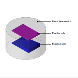
When electroplating, use a solution that includes the component you wish to use. Within that solvent, set the board including the component you wish to electroplate at a positive pole, and set the board you with to electroplate at the negative pole, and run voltage. Then, current will flow, and the component of the positive pole will melt in the solvent, and electroplating for the negative pole side will start.
This document introduces will introduce the electric field distribution in a model with the negative pole geometry facing the positive pole that is not parallel but slanted.
Electric field distribution
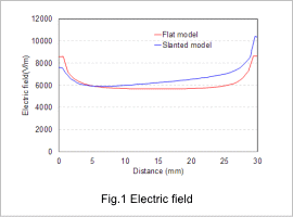
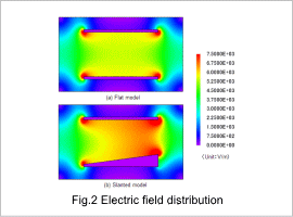
Fig.1 shows the flat model and the slanted model in the electric field graph, and Fig.2 shows the contour of electric field distribution. Also, Fig.1 is measured along the electric pole.
For the flat model shown with the red line, Fig.1 shows that it is symmetrical at 15mm as the center. On the other hand, for the slanted model as shown with the blue line, it can be seen that the electric field gets larger as the distance between positive and negative poles becomes smaller.
Fig.2 shows that biases are occurring in the electric field for slanted model on the negative pole.
Current density distribution
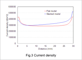
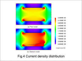
Fig.3 shows the current density graph of the flat model and the slanted model, and Fig.4 shows the contour of the current density distribution.
For the flat model shown with the red line, Fig.3 shows that current density is symmetrical at 15mm as the center. On the other hand, for a slanted model as shown with the blue line, the current density close to the positive pole will be higher. In this case study, since the material property inside the solution is constant, the electric field intensity is in proportion with the amount of the current. For this reason, current density would have the same results.
