*Please prepare a license ID and password for the license administrator.
*It is different from the service for JMAG WEB MEMBER (free membership). Please be careful.
Overview

Recently, PM motors are being applied in home appliances and electric automobiles, and the demand for compactness and high power is increasing. On the other hand, small and high-power motors tend to be affected by high-frequency components due to magnetic saturation and high rotations, which results in increased loss in the motor; therefore, they are also expected to have increased efficiency. In the realization of highly-efficient motors, it will become increasingly important to accurately estimate loss.
In the drive circuit of a PM motor, there are times when current vector control using PWM control (pulse width modulation control) is run. Current waveform that is being supplied by PWM control have carrier harmonic current superimposed on the basic wave control, and with this carrier harmonic current, high-frequency of the magnetic field is applied to the motor core and iron loss occurs. With harmonic components and magnetic saturation of the iron core due to permanent magnets, it will be necessary to evaluate iron loss with magnetic flux density waveform that is different from the conventional sinusoidal alternating current. Also, in a high rotation PM motor, the variable frequency of magnetic flux density becomes increasingly high and the eddy current distribution of the depth direction of the laminated steel sheet due to skin effect becomes difficult to ignore. With these conditions, evaluation using the highly-accurate iron loss calculation function becomes required.
In this example, a hysteresis model accounting for minor loops of the direct current bias magnetism and the lamination analysis function accounting for eddy current distribution in the lamination direction are run simultaneously to evaluate iron loss due to high carrier harmonic components in the IPM motor.
Iron Loss

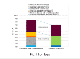
Iron loss is indicated in Fig. 1. The result of the hysteresis model and lamination analysis is compared with the loss analysis result of the conventional iron loss properties.
The eddy current loss obtained by conventional iron loss characteristics is underestimated. The magnetic flux density due to the carrier component during actual driving fluctuates more, so that the magnetic flux density peak is higher than the peak attained for the magnetic flux density used to obtain iron loss characteristics. It is thought that the loss increased because the magnetic permeability decreased, the skin effect was less, and eddy currents were greater. The hysteresis loss is larger than the iron loss in the rotor core. In the rotor core, the positions and areas of the minor loops change mainly due to DC superposition due to magnetic flux. It is thought that this is because the hysteresis model captured these effects more accurately.
The eddy current loss obtained by conventional iron loss characteristics is underestimated. The magnetic flux density due to the carrier component during actual driving fluctuates more, so that the magnetic flux density peak is higher than the peak attained for the magnetic flux density used to obtain iron loss characteristics. It is thought that the loss increased because the magnetic permeability decreased, the skin effect was less, and eddy currents were greater. The hysteresis loss is larger than the iron loss in the rotor core. In the rotor core, the positions and areas of the minor loops change mainly due to DC superposition due to magnetic flux. It is thought that this is because the hysteresis model captured these effects more accurately.
Joule Loss / Hysteresis Loss Density Distribution

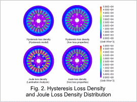
The distribution of joule loss density and hysteresis loss density is displayed in Fig. 2.
It can be confirmed that hysteresis loss is higher in the rotor core surface. This is thought to be the effects of the minor loop. Furthermore, as with the results shown in Fig. 1, the Joule loss density is higher in the lamination analysis than the iron loss density.
It can be confirmed that hysteresis loss is higher in the rotor core surface. This is thought to be the effects of the minor loop. Furthermore, as with the results shown in Fig. 1, the Joule loss density is higher in the lamination analysis than the iron loss density.
Magnetic Flux Density Waveform

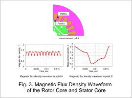
The waveform of magnetic flux density in the rotor core and stator core are displayed in Fig. 3.
Super imposed direct current components that affect the minor loop appear in the magnetic flux density waveform of the rotor core.
Super imposed direct current components that affect the minor loop appear in the magnetic flux density waveform of the rotor core.


