Overview
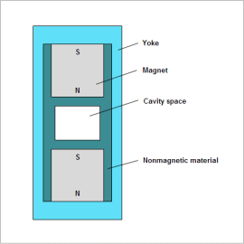
Anisotropic plastic magnets with good magnetic properties need magnetic field orientation. For this reason, a magnetic circuit is created to generate the magnetic flux necessary for magnetic field orientation in the product cavity in the mold used.
Design requirements for the magnetic circuit are that the magnetic flux generated in the cavity has the magnitude necessary and sufficient for the magnetic field orientation, that flux parallel to the analysis target main axis be produced, and that the magnetic circuit be formed as small as possible.
In the case of simple magnetic circuits, these requirements can be met by hand calculation, but FEA is effective for obtaining a generated spatial magnetic flux density distribution, angles, etc. in detail in the cavity. In addition, since trial and error cannot be avoided in an optimum design that minimizes geometry size while satisfying the above requirements, and time is consumed, automation of analysis combined with optimization tools is widely used.
In this example, a use case is presented in which a magnetic circuit of a product-forming mold, in a magnetic field aligned with the mold’s main axis, is optimized, with the mold’s dimensions used as design variables.
Optimization Conditions
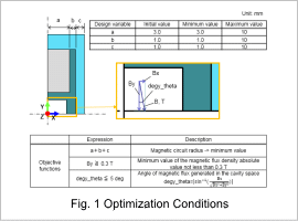
The design variables are the magnet radius a, the non-magnetic material width b, and the yoke width c. Settings are performed for an optimization function that gives the highest priority to minimizing the magnetic circuit radius a+b+c.
In addition, the angle formed by the magnetic flux density B generated in the cavity with respect to the Y-axis and the threshold for the magnitude of B are specified.
In this example, the angle is within an error of 5 deg and the value of B is 0.3 T or more. Also, these variables are used in objective functions.
Optimization Results
The response graphs for the results after optimization is shown.
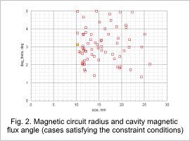
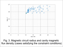
Fig. 2 and Fig. 3 show graphs of Bmin and degy_theta from the objective functions, respectively, vs. the radius of the magnetic circuit. The yellow plot is the optimum value. The optimum value is the minimum value of the radius of the magnetic circuit when the objective function constraints are satisfied.The optimum value plot shown in Fig. 2 and in Fig. 3 are for the same case.
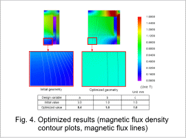
Fig. 4 shows the results magnetic flux density contour plots and flux lines obtained with the initial geometry and with the optimum geometry. The initial values of the variables a, b, c and the values obtained after optimization. It can be seen that in the region of the cavity surrounded by the red rectangle, for the initial geometry some of the flux enters at an angle, however, for the optimized geometry obtained the flux has parallel flux lines and is nearly uniform.
