Overview
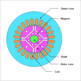
A certain amount of error from processing has to be expected. Processing error itself is not so large that the parts cannot be put together, but even assembly error can cause a minute eccentricity of around 1/10 mm. Analysis that can handle this level of precision is needed to evaluate this kind of minute geometry difference, and electromagnetic field analysis using the Finite Element Method (FEM) is useful because it has the sensitivity for detailed geometry differences.
This Application Note presents how to obtain variations in electromagnetic force according to changes in the amount of rotor eccentricity.
Electromagnetic Force Acting on the Rotor
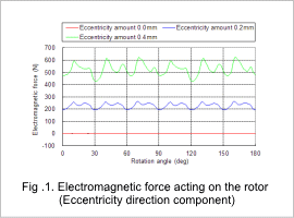
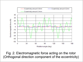
For each amount of eccentricity, the eccentricity direction component of the electromagnetic force acting on the rotor is indicated in fig. 1, and the perpendicular direction component of the eccentricity is indicated in fig. 2.
The graphs show the eccentricity amount becomes larger while the eccentricity direction component of the electromagnetic force becomes smaller. The balance for the orthogonal direction component of the eccentricity for an electromagnetic force is deformed and the amplitude becomes larger.
Electromagnetic Force Acting on the Teeth
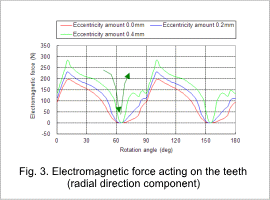
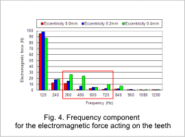
The electromagnetic force of the radial direction component that acts on the teeth where the gap length is most narrow is indicated in fig. 3, and the results for the frequency components of the electromagnetic force displayed in fig 3 is indicated in fig. 4. The radial direction is the positive center direction for a circle.
Fig. 3 shows the larger the eccentricity amount the faster the electromagnetic force changes and is the cause of deformation in the stator. The area in red square as shown in fig. 4 indicate that an increase in harmonic components based on eccentricity causes vibration and noise.
