*Please prepare a license ID and password for the license administrator.
*It is different from the service for JMAG WEB MEMBER (free membership). Please be careful.
Overview
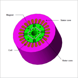
A PMSM usually requires a drive system to operate. There are various types of drive systems such as PAM drive and PWM drive systems.
The concept of PAM drive is simple: a carrier signal modulates a supply signal to generate pulses and controls the amplitude of these pulses by controlling the amplitude of the supply signal. By applying appropriate switching control, this concept can be used in a PMSM drive device. Furthermore, due to the simplicity of the switching control, PAM drive tends to be cheaper and more robust than PWM drive.
In addition, with IPM the back electromotive voltage increases during high-speed rotation, which reduces the torque and the current flowing to the coils. When designing a motor, it is necessary to understand the characteristics for a wide range of operating points. The evaluation of NTI characteristics with FEA at the design study stage contributes greatly to development speed.
In this example, an example of evaluating the performance of an IPM with PAM operation is presented.
Performance Evaluation Results with PAM Drive
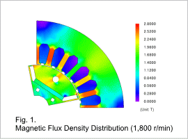
Fig. 1 shows the magnetic flux density distribution at a rotation speed of 1,800 r/min.
It can be seen that the teeth near the coils being excited have a magnetic flux density close to saturation.
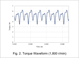
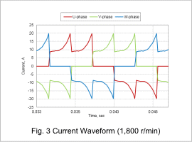
Fig. 2 and Fig. 3 show the torque and current waveforms respectively at an operating point of 1,800 r/min when using PAM drive.
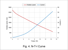
Fig. 4 shows the NTI curves, which predicts motor performance at various operating points. The torque of the IPM motor decreases as the rotation speed increases and increases as the current increases.
