Overview
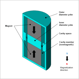
Anisotropic plastic magnets with good magnetic properties need magnetic field orientation. For this reason, a magnetic circuit is created to generate the magnetic flux necessary for magnetic field orientation in the product cavity in the mold used.
The design requirements of the magnetic circuit are that the magnetic flux generated in the cavity obtain a necessary and sufficient magnitude for magnetic field orientation, that uniform and parallel magnetic flux can be obtained, and that the magnetic circuit be formed as small as possible. Furthermore, the price of the magnetic circuit magnets are high compared to the other magnetic circuit components, so reducing the size of the magnets is effective for lowering the cost.
In the case of simple magnetic circuits, these requirements can be met by hand calculation, but FEA is effective for obtaining a generated spatial magnetic flux density distribution, angles, etc. in detail in the cavity. In addition, since trial and error cannot be avoided in an optimum design that minimizes geometry size while satisfying the above requirements, and time is consumed, automation of analysis combined with optimization tools is widely used.
In this example, a use case of magnetic circuit optimization in a metal mold with radial magnetic field orientation used for ring-shaped magnet production is presented.
Optimization Conditions
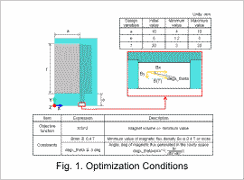
The design variables are a radius a and a height f of one magnet and e is the height of the yoke. The objective function is defined so that the volume πfa^2 of the magnet is minimized.
The constraints specify the maximum limit of the angle formed by the magnetic flux density B generated in the cavity with respect to the X-axis, and the minimum limit of the magnitude of B. In this use case, two constraints are defined. One is that the angle formed with the X-axis be within ±3 deg and the other is that Bx be greater than or equal to 0.4 T.
Optimization Results
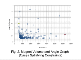
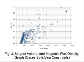
Fig. 2 and Fig. 3 show the graphs of the response values degx_theta and Bmin vs. size obtained by optimization. The cases where the Bmin and degx_theta constraints are not satisfied are not included in the graphs.
The initial value is shown in red and the optimum value is shown in yellow. For the initial value shown in red, size indicating the volume of the magnet is approximately 6,300 mm^3. Whereas for the optimum value shown in yellow the volume of the magnet is 555 mm^3, which is about 11 times smaller than the initial value. The optimum value plot shown in Fig. 2 and in Fig. 3 are for the same case.
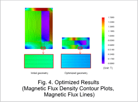
Fig. 4 shows the magnetic flux density contour plot and flux lines for the initial geometry and for the optimized geometry. It can be confirmed that the magnetic flux density of the cavity satisfies both the Bmin and degx_theta constraints, and that a parallel and uniform magnetic flux density can be obtained.
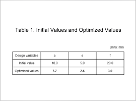
Table 1 shows the initial values of the variables a, e, and f and the same values obtained from optimization.
