Overview

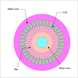
The finite element method is effective in accurately calculating the output power and efficiency of the induction generator. A finite element method accounting for slip and speed allows for detailed analysis and evaluation at various operating points. This makes it easier to find the operating points according to design purposes such as maximum output power and maximum efficiency.
In this example, the relationship between the output power and efficiency of the induction generator is shown here.
Output Characteristics
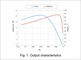
In Fig. 1, the operating points for maximum output power and maximum efficiency can be determined from the maximum output power and maximum efficiency. However, the figure shows that the operating points for maximum power and maximum efficiency do not always match.
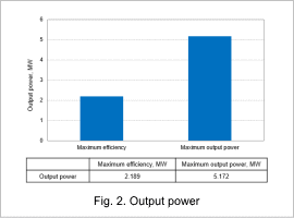
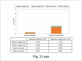
Fig. 2 and Fig. 3 compare the output power and loss at maximum efficiency (slip: -0.017) and maximum output power (slip: -0.061). At maximum efficiency, losses are lower than at maximum output power. On the other hand, output power is approximately 2.4 times greater at maximum output power than at maximum efficiency but loss is approximately 5.7 times greater, indicating that the ratio of loss to output power increases. Therefore, efficiency is lower than at maximum efficiency and the ratio of copper loss in the stator is high among the losses.


