Overview
By using finite element methods, it is possible to determine the causes of electromagnetic excitation force generated from multiple parts that are excitation sources and take measures to prevent noise and a breakdown due to vibration at the design stage before a breakdown occurs.
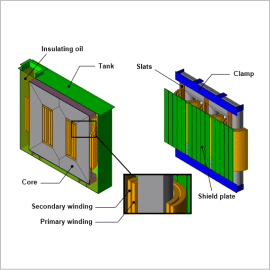
In this example, evaluating vibration caused by electromagnetic excitation in a large transformer. Since large transformers are oil-cooled, in this example the oil, which is the fluid in which the parts are immersed, is treated as an elastic body. The parts that are the source of vibration are mainly the core, tank, and windings, but in this example the core and tank are focused on.
Excitation Force Distribution
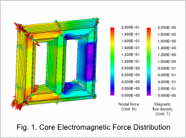
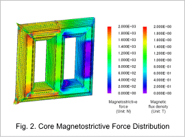
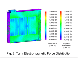
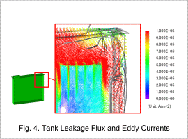
Fig. 1 shows the electromagnetic force distribution of the core, Fig. 2 shows the magnetostrictive force distribution of the core, and Fig. 3 shows the electromagnetic force distribution for the tank. Also, the leakage flux and eddy current distribution for the tank are shown in Fig. 4.
The core and tank excitation sources are focused on. The excitation sources of the core are the electromagnetic and magnetostrictive forces generated in and on the core. Furthermore, the vibration source of the tank is the electromagnetic force affecting eddy currents generated in and on the tank which are generated from leakage flux from the core reaching the tank.
From Fig. 1 to Fig. 3, it is clear that the magnetostrictive force is the dominant force in the excitation force. From Fig. 4, it can be seen that the leakage flux interlinks with the tank generating eddy currents.
Acceleration Distribution
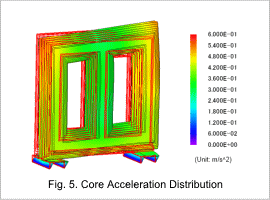
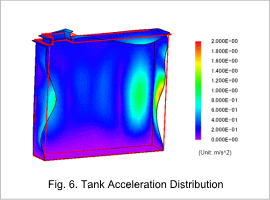
Fig. 5 shows the acceleration distribution of the core, and Fig. 6 shows the acceleration distribution of the tank.
The excitation force was dominated by the magnetostrictive force of the core, but the vibration is seen to be larger in the tank than in the core. It is thought that this is due to the low rigidity of the tank. In addition, since the vibration on the side where the shielding plates are not installed is large, it is thought that by adding shielding plates to this side as well excitation force and vibration can be reduced.
