*Please prepare a license ID and password for the license administrator.
*It is different from the service for JMAG WEB MEMBER (free membership). Please be careful.
Overview

Demand for high fuel efficiency in vehicles has been growing every year, and auxiliary machines like power steering and coolant pumps have been switching to electrical operation to support those needs. This is why the amount of electrical power being used in typical gasoline vehicles is increasing with each passing year, and manufacturers are looking for high-output alternators that can supply this level of electricity. They need to increase the output density, however, because they cannot increase the size of the actuator to correspond with the added generation capacity. They also need to achieve higher efficiency.
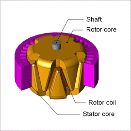
A claw pole alternator generates electricity in the coil on the stator side with the rotor side acting as an electromagnet. The excitation coil on the rotor side is a single phase, and the claw pole is arranged so that it wraps around this coil. The claws that extend from the inside of the coil and the ones that extend from the outside of the coil have poles with different polar characteristics, and they have the same polar structure as a magnet that is arranged with magnetization that alternates between North and South. Because the alternator needs to be designed with a 3D geometry to account for the claw poles and the analysis needs to consider eddy currents generated in the surface of the claw poles, which are made from a metal plate, an electromagnetic field analysis using the finite element method would be the most useful, as it can simulate detailed geometries and account for eddy currents.
This Application Note presents the use of an electromagnetic field analysis to evaluate the output capacity of a claw pole alternator operating at 1500 rpm while accounting for eddy currents in the rotor core.
Eddy Current Density Distribution/ Magnetic Flux Density Distribution
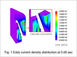
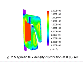
Fig. 1 shows the eddy current density distribution and fig. 2 shows the magnetic flux density distribution.
Eddy current is produced in the surface of the claw pole from the rotor core. These eddy currents produce eddy current losses and reduce the alternator’s efficiency. The eddy currents also effect the magnetic flux density distribution, so they must be taken into account when studying a magnetic circuit at high output.


Output

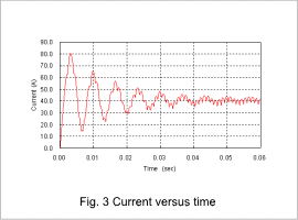
Fig. 3 shows the current versus time characteristic taking into account the effect of a shunt resistance.
The transient phenomena that occur until a steady state are caused by influence from the stator coil’s inductance and the rotor core’s eddy currents, so ripples in a steady state are caused by the commutator circuit.
The alternator output is approximately 41 Ampere, which can be found from the average value of the current waveform at a steady state.


