*Please prepare a license ID and password for the license administrator.
*It is different from the service for JMAG WEB MEMBER (free membership). Please be careful.
Overview
With the increase in price for rare earth magnets, synchronous reluctance motors that do not utilize permanent magnets have been attracting attention for the likes of industrial purposes. Because they do not use permanent magnets or secondary conductors, synchronous reluctance motors can be anticipated to be variable speed motors that are both inexpensive and highly efficient. Efficiency maps are created for both motor design and control design in order to fully comprehend the characteristics of these motors that are capable of drive within such a wide range.
Torque, voltage, and current can be calculated from motor voltage equations and torque equations for estimating efficiency, but there exists the issue of difficulty in estimating iron loss, as well as accounting for the nonlinear magnetization characteristics of the iron core. Through simulations using FEA, however, efficiency maps that account for the effects of iron loss and nonlinear magnetization characteristics can be obtained with ease.
In this example, the efficiency map of a synchronous reluctance motor is created with loss ratios at each operating point also evaluated.
Efficiency Map and Power Factor Map
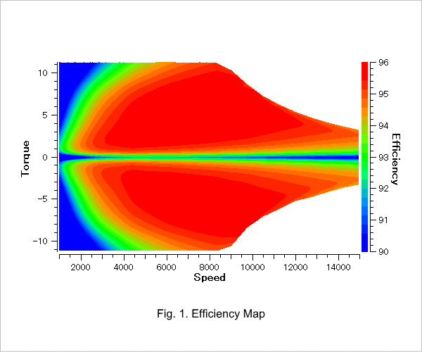
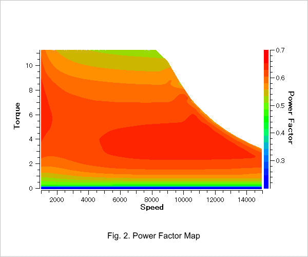
The efficiency map is displayed in Fig. 1, and the power factor map is displayed in Fig. 2.
Motor mode and generator mode efficiency can be understood from Fig. 1.
It can be seen from Fig. 2 that this motor has a power factor of 0.7 or less, which is particularly low in both the high-torque region and the low-torque region.
Loss Ratios at Each Operating Point
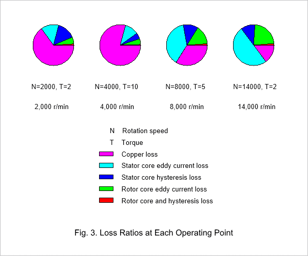
Fig. 3 displays pie charts showing loss ratios at low speed and high load, low speed and medium load, medium speed and medium load, and lastly, high speed and low load.
Copper loss decreases in accordance with load. It can be seen that the loss of both the stator core and the rotor core increases in accordance with rotation speed, with eddy current loss increasing in particular.
Copper loss decreases in accordance with load. It can be seen that the loss of both the stator core and the rotor core increases in accordance with rotation speed, with eddy current loss increasing in particular.

