Overview
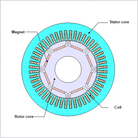
An example of creating efficiency maps is shown in JAC165. In post-processing, PWM-induced iron loss is accounted for in JAC165 but input is sinusoidal, and coil AC loss is ignored. Because power electronics are used for traction motors, ignoring the effects of PWM may lead to overestimating motor performance.
In this example, an IPM motor efficiency map that accounts for PWM-induced AC loss is created, and compared to an efficiency map that does not account for AC loss.
Efficiency Map Not Accounting for AC Loss
Modeling to Account for AC Loss
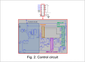
A control circuit is created to account for the effects of PWM. In JMAG, the transient state at the start of the analysis is calculated using the JMAG-RT model, and FEA is run after the steady state is reached, thereby reducing the analysis time.
Efficiency Map Accounting for AC Loss
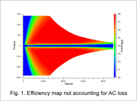
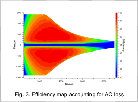
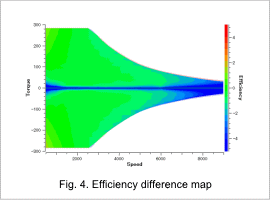
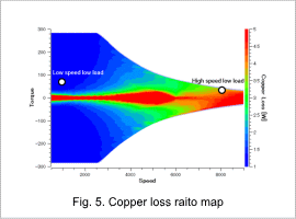
An efficiency map accounting for PWM-induced AC loss is shown in Fig. 3. In addition, a comparison is made for an efficiency map when AC losses are accounted for in Fig. 1 and in an efficiency map when AC losses are not accounted for in Fig. 3. The difference map for efficiency is shown in Fig. 4 and the ratio map for copper loss is shown in Fig. 5.
Fig. 4 shows that the difference between when AC losses are accounted for and not accounted for is approximately 1 point in the low and medium speed ranges. In the high-speed range, the difference is 2 – 5 points or more. This difference is expected to affect accuracy when efficiency reaches a high of 90 % or more, like in traction motors.
Fig. 5 shows that there is a significant difference in copper loss in the high-speed range depending on whether AC losses are accounted for or not. This is believed to have caused the difference in efficiency shown in Fig. 4.
Breakdown of loss components
Check the loss at low-speed low-load and high-speed low-load shown in Fig. 5.
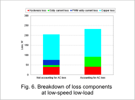
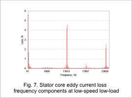
The breakdown of loss components at low-speed low-load is shown in Fig. 6 and the eddy current loss frequency components of the stator core when the AC loss is accounted for is shown in Fig. 7.
The carrier frequency of PWM is 6,000 Hz. Fig. 6 and Fig. 7 show that the PWM harmonic component has a large effect on eddy current loss at low-speed low-load. Note that, in an analysis that does not account for AC loss, PWM-induced iron loss is obtained in post-processing. This reduces the difference compared to when the AC loss is taken into account.
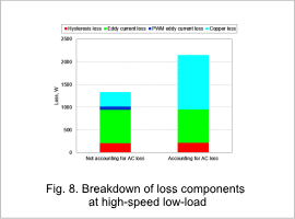
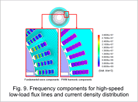
Fig. 8 shows the breakdown of loss components at high-speed low-load and Fig. 9 shows the frequency components of the flux lines and current density distribution when AC loss is taken into account.
Fig. 8 shows that PWM-induced eddy current loss has little effect at high-speed low-load but that there is a large difference depending on whether the AC loss is accounted for in copper loss. Fig. 9 shows that this difference in copper loss is thought to be due to eddy currents caused by leakage flux in the slot.
