*Please prepare a license ID and password for the license administrator.
*It is different from the service for JMAG WEB MEMBER (free membership). Please be careful.
Overview
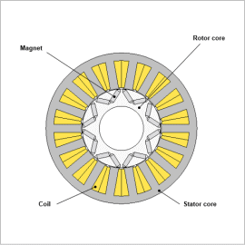
For traction motors, polyphase design is sometimes used with the objective of improving output density, increasing redundancy during drive, and reducing torque ripple. In polyphase design, six-phase drive with two inverters are used. The typical control method is current vector control, and PWM motors are widely used to create command currents.
It is necessary to be aware of iron loss to increase the efficiency of motor drive systems. When power is converted using PWM, carrier harmonics produced by PWM are superimposed on the current and IPM motor core magnetic flux density waveforms, causing an increase in iron loss. Iron loss accounting for PWM carrier harmonics can be evaluated by modeling control circuits that include PWM inverters and coupling them with magnetic field analysis.
In this example, confirming the effects of carrier harmonics on the iron loss of a six-phase IPM motor are explained here.
Operating Point to Evaluate
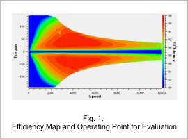
The efficiency map and the operating point for evaluating this motor are shown in Fig. 1.
This evaluates harmonic iron loss at an operating point where rotation speed is 2,800 r/min and torque is 75 Nm. This operating point also has a current amplitude of 76.6 A and a current phase of 36 deg.
This evaluates harmonic iron loss at an operating point where rotation speed is 2,800 r/min and torque is 75 Nm. This operating point also has a current amplitude of 76.6 A and a current phase of 36 deg.
Modeling to Account for Harmonic Iron Loss
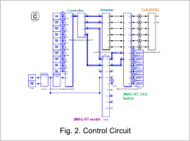
The control circuit is shown in Fig. 2.
The control circuit is created to account for the influence of the PWM. A JMAG-RT model is used in the control circuit. Calculation is performed with the JMAG-RT model when analysis begins in a transient state. Analysis time is then reduced by switching to FEA after reaching a steady state.
The control circuit is created to account for the influence of the PWM. A JMAG-RT model is used in the control circuit. Calculation is performed with the JMAG-RT model when analysis begins in a transient state. Analysis time is then reduced by switching to FEA after reaching a steady state.
Loss Breakdown
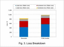
Hysteresis loss and Joule loss that occurs during sinusoidal current drive and PWM inverter drive are shown in Fig. 3.
Loss increases during PWM inverter drive for both the rotor core and the stator core. In particular, there is a large increase in Joule loss approximately 30% more increase for both the rotor core and stator core.
Loss increases during PWM inverter drive for both the rotor core and the stator core. In particular, there is a large increase in Joule loss approximately 30% more increase for both the rotor core and stator core.
Joule Loss/Loss Density Distributions
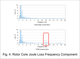
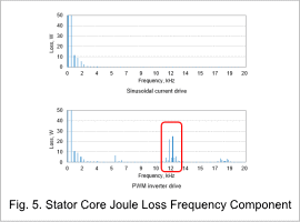
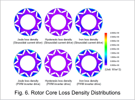
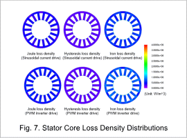
Joule loss frequency components are shown in Fig. 4 and Fig. 5 and loss density distributions are shown in Fig. 6 and Fig. 7. Note that, the vertical axis for Fig. 4 and Fig. 5 are deliberately narrowed to clarify the difference.
Iron loss mainly increases in the secondary component of the PWM carrier frequency (12 kHz) (the red frame in the center of the diagram). It is recognized that the increase in Joule loss during PWM inverter drive is caused by the carrier frequency. Therefore, it is necessary to account for the effects of carrier harmonics when evaluating detailed motor characteristics.
