*Please prepare a license ID and password for the license administrator.
*It is different from the service for JMAG WEB MEMBER (free membership). Please be careful.
Overview
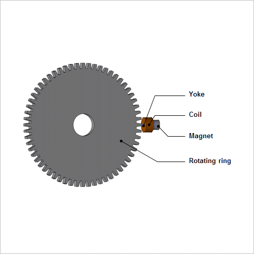
Antilock brake systems (ABS) have become a standard feature in vehicles, so speed sensors are attached to each wheel in order to measure their respective speeds. There are several methods of detecting rotation speed, but magnetic sensors are weather resistant and have a small number of parts because there only needs to be a gear on the rotation side, so they are widely used.
The challenges from a design standpoint are the angle and relative distance between the gear's teeth and sensor, and how to ensure sensitivity and responsiveness when considering the magnetic influence of the surrounding air. In order to proceed with an advance study like this that considers a precise geometry and material properties, an electromagnetic field analysis using the finite element method (FEM) is effective.
This Application Note presents the use of magnetic field analysis to evaluate the variation of the voltage signal of a magnetic speed sensor for a range of air gap distances.
Magnetic Flux Density Distribution
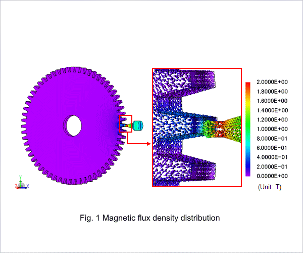
Fig. 1 shows the magnetic flux density distribution at a rotation angle of 5.0 deg when the gap width is 0.5 mm.
The figures show how the magnetic flux from the magnet flows through the yoke and reaches the rotating ring. When the rotating ring rotates, the permeance in the magnetic circuit changes due to the moving teeth. This changes the amount of magnetic flux that passes through the yoke, thus generating the electromotive force in the coil.
The figures show how the magnetic flux from the magnet flows through the yoke and reaches the rotating ring. When the rotating ring rotates, the permeance in the magnetic circuit changes due to the moving teeth. This changes the amount of magnetic flux that passes through the yoke, thus generating the electromotive force in the coil.
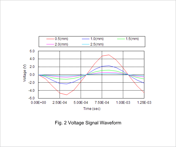
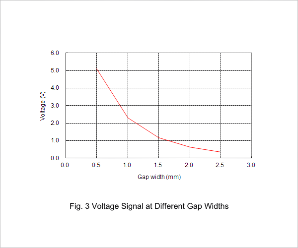
Voltage Signal at Different Gap Widths
Fig. 2 shows the voltage signal waveform at each gap width, and fig. 3 shows the peak value of the voltage signal as a function of the gap width.
When the gap width is large, the voltage is small because the permeance is smaller compared with a small gap width, and then the magnetic flux amount that flows through the yoke and the coil becomes smaller.