Overview
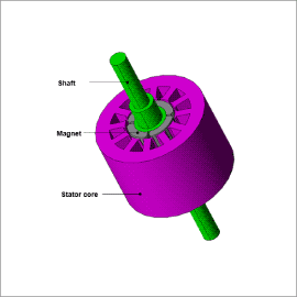
A simulation using the finite element method can obtain the losses in a motor with a layer short and visualize changes in magnetic circuit without any prototype testing.
This case study compares the magnetic flux density distribution and losses of a three-phase SPM motor with and without a layer short.
Current, Magnetic Flux Density, and Losses
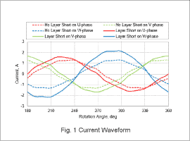
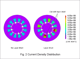
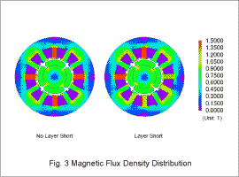
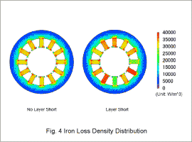
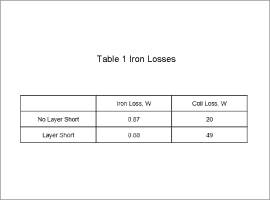
The analysis obtains the results below for an SPM motor without a layer short and an SPM motor with a layer short on the W-phase. Fig. 1 illustrates the current waveform. Fig. 2 presents the average current density distribution (absolute values) for one cycle. Fig. 3 shows the magnetic flux density distribution. Fig. 4 indicates the iron loss density distribution. Table 1 outlines the iron loss and coil loss values.
The SPM motor without the layer short has a balanced three-phase current waveform as illustrated by Fig. 1. However, the SPM motor with a layer short has an unbalanced waveform, which shows the W-phase has a particularly large amplitude. For this reason, the current density of the W-phase is high as indicated by Fig. 2. The unbalanced waveform also skews the magnetic flux density and iron loss density toward the stator teeth as presented in Fig. 3 and Fig. 4.
The layer short has almost no affect on the iron losses but does increase the coil losses as indicated by Table 1. This is due to the large current flowing in the location of the layer short.
