Overview
For this reason it is necessary to set up the overhang amount properly while looking at the trade-off between an increase in torque and an increase in losses. A magnetic field analysis using the finite element method (FEM), which can obtain the relationship between a three dimensional magnetic field and eddy currents, is an effective method for an advance study.
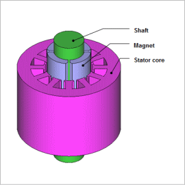
This Application Note presents the use of a no-load iron loss analysis of an SPM motor with and without an overhanging magnet.
Magnetic Flux Density Distribution, Eddy Current Density Distribution
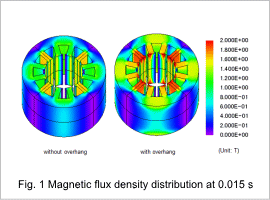
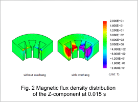
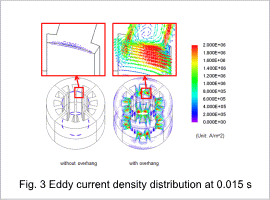
Fig. 1 shows the flux density distribution of the stator core with and without overhanging magnet, fig. 2 shows the flux density distribution in the lamination direction, and fig. 3 shows the eddy current density distribution.
The flux density is higher around the surface of the stator core because the overhanging magnet increased the flux in the in-plane direction and the lamination direction. The eddy currents generated around the surface of the tooth tips also penetrates into the interior of the stator core because of the increase in magnetic flux in the lamination direction.
Iron Loss Comparison with and without Overhanging Magnet
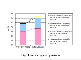
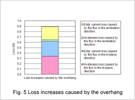
Fig. 4 show the values of the eddy current loss and hysteresis loss from the magnetic flux in the lamination direction and in-plane direction, which was obtained from a magnetic field analysis and an iron loss calculation. Fig. 5 shows the amount of increase in the losses from overhang.
Losses generated by magnetic flux in the lamination direction and in-plane direction both increased when overhang was applied.
