*Please prepare a license ID and password for the license administrator.
*It is different from the service for JMAG WEB MEMBER (free membership). Please be careful.
Overview

The electromagnetic force acting on a motor produces vibrations and noise as electromagnetic excitation force. The vibrations produced by electromagnetic force acting on the teeth of the stator core transfer through and cause the case around the outside of the stator core and other peripheral parts to vibrate.
Simulation tools to analyze NVH in early evaluations are advantageous for assessing the impact the excitation force produced by the motor has on the noise and vibrations of the entire system. That is why NVH evaluation tools must take into account the excitation force that produces these vibrations. Finite element analyses of motors can obtain this excitation force.
The electromagnetic force acting on the teeth of a motor rotor that has step skew differs due to the position of the teeth at each step. Simulations need to analyze the electromagnetic force for each position of the teeth to more accurately obtain the electromagnetic excitation force.
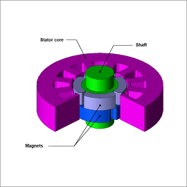
This case study runs a magnetic field analysis of an SPM motor with step skew to obtain the electromagnetic force acting on the teeth of the stator core to verify the electromagnetic force waveform.
Magnetic Flux Density Distribution

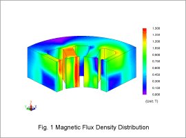
Fig. 1 indicates the magnetic flux density distribution at the initial rotor position. The rotor magnet skew changes the magnetic flux density distribution on the upper and lower regions of the teeth in the axial direction. The varying magnetic flux density distribution causes the electromagnetic force acting on the upper and lower regions of the teeth to differ as well.
Waveform of Electromagnetic force Acting on Teeth
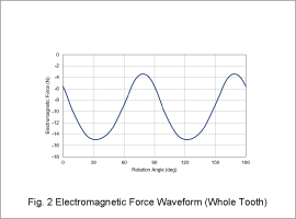
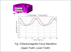
Fig. 2 presents the waveform of electromagnetic force acting on the whole tooth when focusing on a single tooth. Fig. 3 indicates the waveform of electromagnetic force acting on the upper and lower regions of the tooth in the radial direction. The waveform of the electromagnetic force acting on the upper and lower regions of the tooth have a 15 deg phase angle difference because the skew angle of the rotor magnets is 15 deg. A waveform of the electromagnetic force acting on the whole tooth clearly does not show this phase angle difference.


