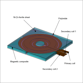
Overview
However, miniaturization and higher frequencies increase leakage flux, which lowers the coupling coefficient and drives up losses. Electromagnetic field analyses are advantageous for evaluating transformer designs. In particular, electromagnetic field analyses that account for the parasitic capacitance predominately seen in high-frequency regions can identify self-resonant frequencies and changes of the impedance at high-frequency bands.
This case study models a transformer for an LCC resonant converter as an example for obtaining the frequency characteristics of the resistance and impedance.
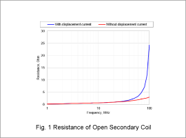
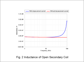
Resistance/Inductance of Open Secondary Coil
Fig. 1 presents the resistance for the open secondary coil. Fig. 2 outlines the inductance.
The resistance and inductance increase when taking into account the displacement current. This increase is particularly significant around 30 MHz.
The effect of the parasitic capacitance becomes dominate in high-frequency domains. The composite impedance of the inductance and capacitance rapidly increases as the frequency approaches resonance. As a result, the actual inductance that is measured appears larger.
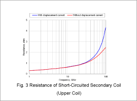
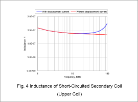
Resistance/Inductance of Short-Circuited Secondary Coil (Upper Coil)
Fig. 3 presents the resistance for the short-circuited secondary coil (upper coil). Fig. 4 outlines the inductance.
The resistance increases as the frequency rises, and the effect of the displacement current becomes large at high-frequency bands. The inductance temporarily declines at around 10 MHz to 30 MHz as the frequency rises before rapidly increasing. Eddy currents produced in the coil cancel out the leakage flux at around 10 MHz to 30 MHz, which is why the inductance drops. However, the impact of the parasitic capacitance becomes more significant as the frequency rises, which is why the inductance rapidly increases thereafter.
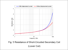
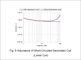
Resistance/Inductance of Short-Circuited Secondary Coil (Lower Coil)
Fig. 5 presents the resistance for the short-circuited secondary coil (lower coil). Fig. 6 outlines the inductance.
The resistance increases as the frequency rises, and the effect of the displacement current becomes large at high-frequency bands.
The inductance temporarily declines at around 10 MHz to 30 MHz as the frequency rises before rapidly increasing. Eddy currents produced in the coil cancel out the leakage flux at around 10 MHz to 30 MHz, which is why the inductance drops. However, the impact of the parasitic capacitance becomes more significant as the frequency rises, which is why the inductance rapidly increases thereafter.
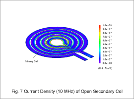
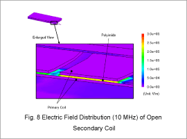
Current Density/Electric Field Distributions
Fig. 7 illustrates the current density distribution for the10 MHz power supply frequency. Fig. 8 presents the electric field distribution.
As illustrated by Fig. 4.7, the current crowds at the corners of the winding. The skin effect causes this phenomenon. The current crowding reduces the effective cross-sectional area of the winding, which in turn increases the resistance.
As shown by Fig. 4.8, the parasitic capacitance is high in the primary coil made of polyimide. This is particularly significant in high-frequency domains.
Computational Costs
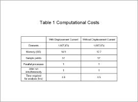
Table 1 outlines the computational costs of each analysis.

