Overview
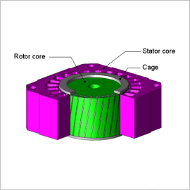
Applying skew generally affects the flow of magnetic flux in the axial direction, making it complex. This is why an analysis that can correctly verify the three dimensional magnetic flux flow is necessary to obtain an advance evaluation of the skew’s effects.
This Application Note presents a comparison of the torque waveforms of three phase squirrel cage induction motors with and without torque, and introduces the effects of using skew to reduce torque variations. Changes in the higher components caused by skew are also displayed by separating the frequencies of the secondary current, which causes the torque variations.
Torque Variations
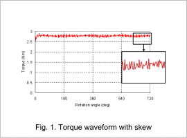
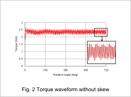
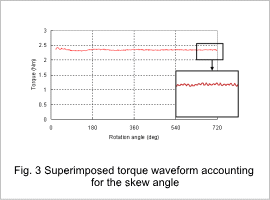
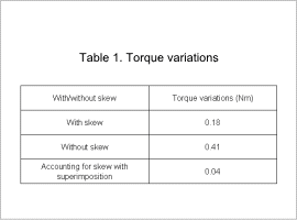
The torque waveform with and without a cage that has skew is indicated in fig. 1, fig. 2, and fig. 3, and the size of the torque variations is indicated in Table 1. The results in fig. 1 are obtained with a 3D analysis. The results in fig. 2 are obtained with a 2D analysis. The results in fig. 3 combine the 2D analysis results with the skew angle. An induction motor produces torque from the rotating magnetic field of the stator coil and the induction current of the rotor. The torque variations can be reduced by using a cage that has skew. Fig. 3 shows that the superimposition of the 2D analysis and the skew angle makes it easy to display the reductions in torque ripple from skew and the approximate generated torque.
Current Density Distribution
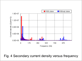
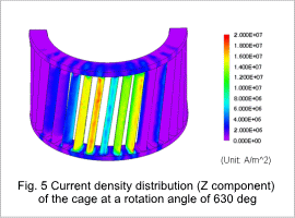
Fig. 4 shows the secondary current density versus frequency, and fig. 5 shows the current density distribution of the cage. The harmonic components of the current produced by the harmonic magnetic flux in the stator are reduced by using a cage with skew as indicated by the secondary current density versus frequency. This is why the torque variations have been reduced as described above.
