*Please prepare a license ID and password for the license administrator.
*It is different from the service for JMAG WEB MEMBER (free membership). Please be careful.
Overview

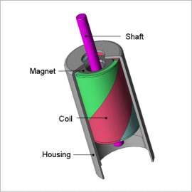
As their name implies, coreless motors have a rotor that lacks a core and is made of only a coil. For this reason, there is no core to produce iron loss in the rotor, and its moment of inertia is small. They can be controlled easily because their characteristics are linear and they have small torque ripples, but they are not versatile enough to produce a large amount of torque. This is why they are often used in small precision equipment that requires high rotation speeds and good responsiveness. The rotor coil is hard to construct because it is made of only a coil. It is important to design the coil’s twist angle to be able to produce torque. The model needs to be made precisely because coreless motors are used in compact equipment and because the detailed geometry of the parts can affect the characteristics.
In order to carry out these evaluations, the coil’s twist needs to be accounted for accurately in three dimensions. An electromagnetic field analysis using the finite element method (FEM) is necessary to accomplish this because it can evaluate the distribution of the electromagnetic force produced in the magnetic circuit in detail.
This Application Note presents an evaluation of the torque waveform of a coreless motor when current is running.
Torque Waveform/Current Waveform
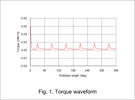
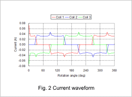
The torque waveform and current waveform are shown in fig. 1 and fig. 2. A smooth rotation can be achieved because the rotor doesn’t have an iron core, as indicated in fig. 1. The average torque is also indicated at 0.022 mN·m. A ripple has occurred in the torque waveform calculated by this analysis, but this is caused by the varying contact of the brush and commutator as indicated in fig. 2.


Current Density Distribution/Lorentz Force Density Distribution

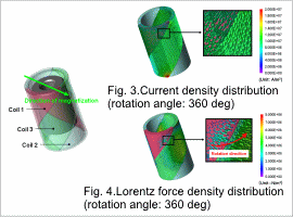
The current density distribution of the coil at a rotation angle of 360 deg is shown in fig. 3, and the Lorentz force density distribution is shown in fig. 4. A current flows in coil 1 and coil 3 without flowing in coil 2 when the rotation angle is 360 deg, as indicated in fig. 3. The currents also flow in opposite directions of one another. The box inside of fig. 4 shows that coil 3 generates force in the rotation direction, but coil 1 generates force both with and against the rotation direction. This occurs because the direction of the current differs while the directions of the magnetic fields for each phase coil are the same.


