*Please prepare a license ID and password for the license administrator.
*It is different from the service for JMAG WEB MEMBER (free membership). Please be careful.
Overview

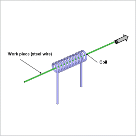
Steel wires are made to be resistant to wear and tear. This is accomplished by giving them a certain degree of flexibility by maintaining their inner toughness while increasing the hardness of their surfaces. By using high-frequency induction heating, which is a type of surface hardening method, the steel wire is heated rapidly on only its surface by a high frequency power source. This process also has many other benefits, such as providing a clean working environment because it uses electrical equipment, being very efficient, and providing uniform results for each product. This is why it is being aggressively implemented in the field. On the other hand, when the heating target is a long steel wire, it is heated rapidly while passing through the heating coil. For this reason, there are several factors that need to be studied when assigning a heating amount to correspond to the speed at which the wire passes through the coil. Examples of these are: the arrangement of the heating coils so that it can fulfill the necessary heating amount, and how to adjust the current’s frequency and size.
This Application Note presents a simulation of the heating conditions of a sufficiently long steel wire that passes through a heating coil. The eddy currents produced from the high frequency’s varying magnetic fields are uneven on the steel wire’s surface, so its material properties change due to increases in temperature. This is why it is necessary to approximate the amount of heat generated in a numerical analysis based on the finite element method (FEM) in order to handle the detailed phenomena.
This Application Note explains how to create a numerical analysis model when obtaining the optimum coil geometry, current conditions (power supply frequency, current value), and movement speed. It also shows how to evaluate whether the model fulfills the target heating speed by analyzing the elevated temperature process.
Eddy Current Loss Density Distribution

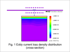
Fig. 1 shows the eddy current loss density distribution of the work piece and the coil. The magnetic field made by the coil changes with time, generating eddy currents in the work piece. In induction heating these eddy currents become heat sources and heat up the work piece. At high frequencies, the work piece is influenced by the skin effect, making it so that the eddy currents are distributed in the surface.
Temperature Distribution of the Steel Wire

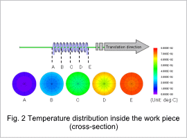
Fig. 2 shows the temperature distribution at each position of the work piece.
Temperature Variation of the Steel Wire

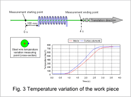
Fig. 3 shows the temperature variation at the surface and inside of the work piece.
According to the graph, the maximum temperature is around 750 deg C both at the surface and inside the work piece. It is apparent that the surface is heated first.
According to the graph, the maximum temperature is around 750 deg C both at the surface and inside the work piece. It is apparent that the surface is heated first.


