Overview
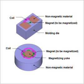
Both the orientation process and the magnetization process need to be accounted for in order to evaluate a magnet’s magnetization state accurately. Consequently, it is extremely difficult to study a magnetizing state by obtaining the behaviors of the molding die, magnetization device, and magnetization current with manual calculations. Running a magnetic field analysis simulation that uses the finite element method (FEM) it is possible to calculate the magnetic field orientation and magnetization field from the material properties, equipment geometry, and applied current. One can also run an analysis that uses the magnetization state inside the magnet based on these results.
This Application Note explains how to obtain a magnet’s surface magnetic flux density distribution while accounting for the orientation and magnetization processes.
Magnetic Field Orientation Distribution / Magnetization Field Distribution
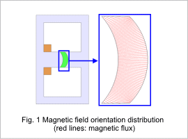
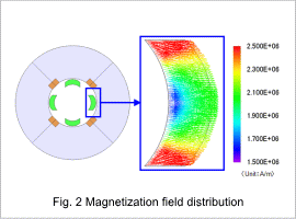
The magnetic field orientation distribution is shown in fig. 1, and the magnetization field distribution is shown in fig. 2. As can be seen in fig. 1, the magnetic field orientation distribution is almost entirely radial distribution. For this orientation, the magnetization state of the magnet is determined by applying the magnetization field shown in fig. 2.
Magnetization Distribution / Surface Magnetic Flux Density Distribution
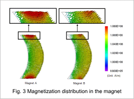
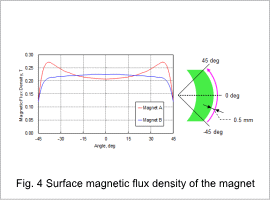
Fig. 3 shows the magnetization distribution in Magnets A and B. Magnet A is the magnet that was magnetized by accounting for the magnetic field orientation shown in fig. 1. Magnet B is a magnet that was magnetized with an ideal radial orientation. The magnetic flux density distribution at a distance of 0.5 mm from the surface of a magnet that has been placed in air is shown in fig. 4.
From fig. 3, it can be seen that there is greater magnetization at the ends of Magnet A than of Magnet B. This is because the orientation at the ends of Magnet A shown in fig. 1 is more similar to the magnetization field distribution shown in fig. 2 than with Magnet B. From fig. 4, it can be seen that the surface magnetic flux density is higher in Magnet B than Magnet A at the center of the magnetic poles. This is because the orientation at the center of the poles in Magnet A shown in fig. 1 differs more from the direction of the magnetization field shown in fig. 2 than it does with Magnet B. As can be seen from the results in fig. 3, the surface magnetic flux density distribution at the ends of the magnets differs greatly.
This is why in order to evaluate the magnetization state of a magnet accurately, the magnetic field orientation and magnetization field need to be taken into account.
