*Please prepare a license ID and password for the license administrator.
*It is different from the service for JMAG WEB MEMBER (free membership). Please be careful.
Overview
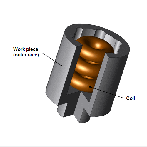
Constant velocity joints are used in the connections at each end of a drive shaft in a vehicular drive system. The inside of the outer race of a constant velocity joint makes direct contact with steel balls or rollers on the inner race, so it needs to have increased hardness to improve its ability to resist wear and tear. On the other hand, its inside needs to retain its toughness in order to maintain its flexibility as a part. High-frequency induction hardening is used as a heat treatment method that hardens only the surface of a product. With this method, using a high-frequency power supply makes it possible to heat the surface locally and rapidly. This process also has many other benefits, such as providing a clean working environment because it uses electrical equipment, being very efficient, and providing uniform results for each product. This is why it is being aggressively implemented in the field. It is difficult to predict the hardening of the inside of a constant velocity joint because its uneven geometry makes eddy currents and magnetic flux flow in a complex manner.
With interior hardening like the kind used in this example, the heating coil design must follow spatial constraints. The eddy currents that are generated from a high-frequency varying magnetic field are offset on the surface of the part's interior, so the material properties change a great deal as the temperature rises. This is why it is necessary to predict the amount of heat generated in a numerical analysis based on the finite element method (FEM) in order to handle the detailed phenomena.
This Application Note shows how to run an analysis of the elevated temperature process by using the geometry of a coil to evaluate whether or not the target temperature conditions are fulfilled.
Joule Loss Density Distribution
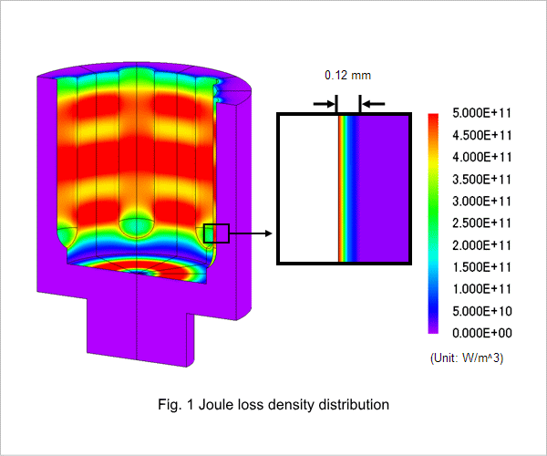
The joule loss density distribution produced in the outer race is shown in fig. 1. Eddy currents are generated in the outer race by time variations in the magnetic field created by the coil. In induction heating, these eddy currents become a heat source for the work piece. At high frequencies the work piece is strongly affected by the skin effect, so the eddy currents are distributed near its surface.
Temperature Distribution
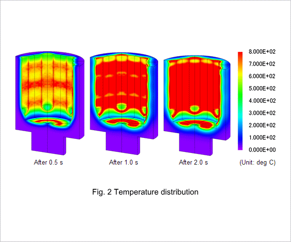
The temperature distribution of the outer race is shown in fig. 2. The eddy currents cause heat to generate in the outer race, so the temperature rises as time passes. At 2 s most of the inside of the outer race reaches the Curie point of 800 deg C, but there is variation in the temperature distribution. Improvements need to be made to the coil geometry in order to achieve uniform heating on the inside of the outer race.

