 Fig. 1
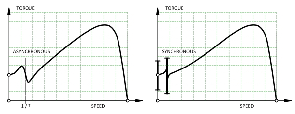
Fig. 1 shows two types of irregularity in the speed/torque characteristic of an induction motor — the asynchronous torque dip and the synchronous torque dip. These are sometimes called “cusps” or “hooks”. If the speed/torque characteristic of the load intersects with the motor curve in the region of a dip, the motor can run at a fraction of its normal speed (“crawling” or “cogging”) and fail to start normally. This condition is generally very noisy. The motor may even fail to start (“standstill locking”).
These problems were met in the earliest days of the development of the induction motor. Rules of thumb were developed, often based on practical experience, especially relating to the combination of rotor and stator slot-numbers. Some companies built and tested dozens of motors with different slot-numbers, different degrees of skew, and even different numbers of phases; but published data is very rare in the literature. Even today, the problem does not have a unique prescriptive solution, and various authorities are not in complete agreement. There remains much art, and testing remains essential.
Fig. 1 shows only one asynchronous torque dip, due to the 7th space-harmonic of the stator MMF which rotates forwards at 1/7 of the synchronous speed. This particular dip is due solely to the MMF harmonic and is independent of the slotting. In a 3-phase motor the 5th MMF harmonic may have a comparable effect, but it rotates backwards (at 1/5 of the synchronous speed) and therefore is not troublesome in normal motoring operation. Although the effects generally diminish with increasing harmonic order, higher-order asynchronous torque dips can arise through interaction with permeance harmonics.
A synchronous torque dip or “locking torque” is a vernier reluctance torque associated with slotting on both sides of the air-gap, which tends to pull the stator and rotor teeth together in groups. The effect is equivalent to a vernier reluctance motor embedded in the main motor (Lee [1963]), indeed some of the analysis relating to slot-numbers is quite similar to the same considerations in stepper motors and switched reluctance motors.
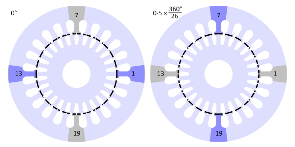 Fig. 2
 Fig. 3
Since the 1920s, the analysis of parasitic torques has relied heavily on Fourier’s series (not the FFT!) to find the spatial harmonics of the winding distribution and the slotting. This works well, but the question of a “safe” combination of stator and rotor slot-numbers can be lost in the mathematics, particularly for the synchronous torques.
Fig. 2 shows a 24-slot motor with 26 rotor bars: \(Z_S = 24\) and \(Z_R = 26\). In the left-hand diagram a rotor tooth is perfectly aligned with a stator tooth on the x-axis: tooth 1 at 0° and tooth 13 at 180°. At these positions the “aligned” condition prevails, labelled \(\mathsf{A}\) in the more detailed view in Fig. 3. Any space-harmonic MMF of the stator oriented along the x-axis would lock the rotor in this “detent” position. The terms “detent position” and “detent torque” are standard terms in connection with vernier reluctance motors and stepping motors, and it is helpful to borrow them here.
Also in the left-hand diagram the stator teeth 7 and 19 at ±90° are perfectly aligned with the centre-line of a rotor slot. At these positions we find the “unaligned” condition, labelled \(\mathsf{U}\) in Fig. 3.
The detent torque is zero in the aligned and unaligned positions, but at any other position it tends to advance the rotor to the nearest aligned position. This principle is also well known in the theory of vernier reluctance motors.
In the aligned position the overlap between a stator tooth and a rotor tooth is maximum, whereas in the unaligned condition the stator tooth is midway between two rotor teeth. The stator tooth has the same overlap with both of these rotor teeth, but any rotation away from that position produces a re-alignment torque that tends to increase the overlap with one rotor tooth while decreasing the overlap with the other one. The overlaps are shaded in Fig. 2 to assist in the visualization of this behaviour.
In the right-hand diagram in Fig. 2, the rotor has moved one-half a rotor slot-pitch, that is, 0·5 × 360/26 = 6·923°. The aligned condition is now found at ±90° (teeth 7 and 19), while the unaligned condition is found at teeth 1 and 13 (0 and 180°). During this rotation through one-half a rotor slot-pitch, imagine the fundamental MMF wave rotating in the same direction through 90°. The “detent” position is now at 90°. With continuous rotation the detent torque advances the rotor forwards at a “vernier” or sub-synchronous speed which is exactly 6·923/90 = 1/13 of the synchronous speed of the field.
There are in fact six aligned conditions arising in the 90° we have been considering. These take place successively on adjacent stator teeth and adjacent rotor teeth. In the time taken for the field to advance one stator slot-pitch, \(2 \pi / Z_S\), the rotation of the rotor is only the difference between the slot-pitches, that is, \(2\pi /Z_S – 2\pi / Z_R\). If the synchronous speed is \(n_S\) rev/sec and \(n_R\) is the speed of the rotor, then by equating the times taken for the respective rotations we get
\(\LARGE \frac{2\pi/Z_S – 2\pi/Z_R}{n_R} = \frac{2\pi/Z_S}{n_S} ,\)(1)
from which
\(\LARGE \frac{n_R}{n_S} = \frac{Z_R – Z_S}{Z_R} ·\) (2)
When can this condition arise?
Fig. 2 shows a pattern of alignments arising in symmetric groups, and this seems inevitable when \(\vert Z_S – Z_R \vert = 2\). However, it is not difficult to imagine a 4-pole pattern of alignments, or a 6-pole pattern. This implies that the enabling condition is \(\vert Z_S – Z_R \vert = 2p\), where \(p\) is the number of pole-pairs. Another way of expressing this is
\(\LARGE \frac{Z_R}{2p} = \frac{Z_S}{2p} \pm 1 , \) (3)
which is the form given by some authors. If \(Z_R > Z_S\) the rotor rotates in the same direction as the MMF, but if \(Z_R < Z_S\) it rotates in the opposite direction. This is apparent from eqn. (2), and is another characteristic in common with vernier reluctance motors.
Another “locking” condition arises at standstill if \(Z_S = Z_R\), when every stator tooth is aligned with a rotor tooth. In this case the detent torque is enormous and the motor will not start. Many other slot-combinations can cause trouble with synchronous locking torques, but the ones considered here are certainly among the most important.
In practice we expect that the synchronous locking torques will be significantly reduced by skewing, and/or when the rotor slot-openings are small or zero. This helps to explain why rules based on eqn. (3) and others are often broken. However, there is no simple prescription for the optimum amount of skew, because skew may be needed to compensate other effects, such as the asynchronous torques arising from stator MMF slot-harmonics. Moreover, even where “exact” harmonic analysis is available, the effects of skewing can be made unpredictable as a result of interbar currents flowing through the rotor laminations, and by variations in the saturation level along the length. Scope for further analysis? Plenty!
Further reading — Lee C.H., Vernier Motor and Its Design, IEEE Transactions on Power Apparatus and Systems, 82 (66), pp. 343-349, 1963.

