 Fig. 1
In this series of Engineer’s Diary, the topics are selected by following the letters of the alphabet, giving an almost random walk through the field of electrical engineering. ‘I’ is next…; so let’s think about insulation.
When we think of insulation, what is often uppermost in our minds is the risk of insulation failure, and how to avoid it.
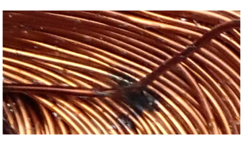
Fig. 1 shows an example — a small blackened area in the midst of an array of strands of enamelled magnet wire in the end-windings of a small motor. This blackened area was discovered by parting the wires with a wooden tool rather like a large chopstick with a chiselled end. We had a faulty motor, and we were searching for the damage. One strand can be seen well out of position as a result of the digging and probing. To the untrained eye, this small area seems to show only a small area of damage. Indeed the blackened area is small — about the same diameter as a chopstick. But the entire winding is ruined by this single-point failure, and the winding must be stripped out and completely rewound before the motor can be used again. In many cases, this is not practicable and the motor will be permanently scrapped.
Most of the time when we design electric machines, we start with a sizing procedure, followed by design calculations in which we predict the performance. As machine designers we are often preoccupied with flux-densities, current-densities, equivalent-circuit impedances, efficiency, and control; and of course we pay a great deal of attention to the losses and we try to calculate the temperature rise in various parts of the machine. In this approach it seems we often pay little attention to the insulation, except of course to follow the rules and standards relating to the maximum allowable temperature at any point in the machine. This temperature is generally defined by the insulating materials themselves, which are classified in the standards into the familiar lettered classes, B, F, H, R and so on, including many subsidiary classes. So for example if the IEC standard says that a certain class of insulation has a certain maximum hot-spot temperature, we strive to ensure that that temperature will not be exceeded in normal service. Most of the electromagnetic and thermal design calculations are bounded by this temperature limit, and they can be accomplished with a high level of precision and confidence using modern numerical analysis tools.
However, once the machine is built and delivered to the customer, the designer has lost all control not only of the winding temperature but of all factors that might affect the life of the insulation. Temperature is only one of many relevant factors. Vibration can damage insulation through ‘fretting’ (rubbing action on a microscopic scale); external short-circuit faults can cause forces large enough to distort the end-windings and even rupture them in large machines; chemical degradation can arise through contamination of the local atmosphere by vapour or dust or even fluids that are hostile to the insulating material; excessive ambient temperature can raise the winding temperature beyond its design limit; and steep-fronted voltage waves (caused by inverter switching or even the action of contactors and circuit-breakers) can cause breakdown or partial breakdown. In addition, there is a natural aging process that is accelerated by temperature, even within the nominal design limits.
As analysts and machine designers, equipped with powerful numerical analysis software, how should we react to an insulation failure event in one of our motors, such as the example in Fig. 1 ?
We can think of three answers to this question. First and foremost, we should check our design calculations (together with as much relevant test data as we can collect) to make sure, as far as possible, that failure could not or should not have occurred as a result of excessive temperature.
But the failure in Fig. 1 is almost certainly not the result of excessive temperature. There is no discolouration of the wire enamel, and in any case excessive temperature should be detected by temperature-sensing transducers that activate the circuit-breaker or at least a warning indicator. A more likely cause is electrical breakdown, which tends to be very localised. When it occurs, it can be catastrophic, even though the damage may be on a small scale as in Fig. 1. In this case the insulation failure would have led to a local short circuit followed by an open-circuit due to the melting of the conductors; the protective elements in the control circuit disconnected the motor quickly and safely, preventing any further damage or maloperation. It is or course the case that early warning is sometimes possible, by means of surge testing or corona detection.
But that brings us to the second answer to the analyst’s question: precisely how did that failure occur? Of course this is another question in answer to the original question; but the point is that analytical tools can help greatly in diagnosing the cause of failure, even when they provide only part of the story and have to be used with physical observations, experiments, additional tests, and deductions from experience. In this case the failure occurred at a particular point in the winding, somewhere along the wire. It is possible with simple measurements to determine where along the wire the failure is located. And then in principle it is possible to set up a numerical analysis of the propagation of a steep-fronted voltage wave and its reflections inside and outside the winding, at least to demonstrate that the transient voltage stress is not uniform along the winding, but contains high local peak values that travel along the wire. It might be difficult to do this in great detail with a random winding such as the one in Fig. 1; but many important windings are geometrically much simpler and more regular — we have only to think of the hair-pin windings used in automotive traction motors, or the form-wound coils used in large machines. In those cases there is a better chance of being able to predict the transient electrostatic voltage distribution resulting from switching events external to the machine. The analogy with an electrical transmission line or a cable is obvious, and the principles of analysis are the same.
The third answer to the analyst’s question is the idea that we can calculate the capacitance of the winding. Like the inductance, the capacitance is a distributed quantity, being spread throughout the winding. In a transmission line, the propagation of transients depends very much on the way in which the capacitance and inductance are distributed along the line (including discontinuities and additional components such as transmission towers, joints, and transformers and other connected equipment). If we know the geometry of the winding and we know the dielectric properties of the insulating materials and any air-spaces and oil-flms in bearings, then in principle we should be able to calculate the distributed capacitance, at least in a simplified model. This analysis may be helpful in relation to the propagation of transients and harmonic components of current, which do not flow simply through the conducting path of the windings but pass instead through complex and irregular ways that often cannot be foreseen. One adverse consequence is the phenomenon of bearing currents, which can cause a great deal of trouble through pitting and general degradation. But transient and harmonic components of current can also increase the stress on the insulation itself. These components of current are unavoidable, and sometimes severe, in inverter-fed machines.
It is not only the internal distribution of capacitance that is of interest, but also the total capacitance lumped at the terminals. Together with a certain parameter representing the transient or high-frequency inductance, this determines the surge impedance which is important in reckoning the reflection and transmission of steep-fronted voltage waves at the terminals (as they arrive many thousands of times per second in inverter-fed machines). This is especially important when long cables are used, because the coincidence of reflected and transmitted wavefronts can cause large local increases in voltage; (“first-turn failure”).
None of these purely analytical operations requires any expert knowledge of the physical properties of insulating materials. So the traditional division of expertise between the machine designer and the insulation specialist need not be disturbed, while both stand to benefit from the power of advanced analysis. We can see plenty of scope for numerical analysis, and it is clear that it will be 3D, transient, and geometrically complex, although it is likely that material characteristics can be represented by simple linear functions and constants (unlike the complex representations needed to model magnetic nonlinearity, hysteresis, and eddy-current loss in laminated core plate).
Reflecting on the overall message of this Diary, we started with a topic (insulation) that we don’t often consider, and we ended up considering a huge potential field of numerical analysis. It is not that this field is completely neglected, but it does seem to receive relatively little attention.


