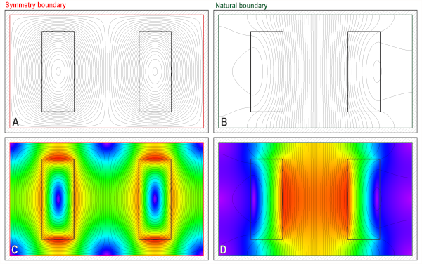
 Fig. 1 Application of Symmetry boundary (red) and Natural boundary (green)
Continuing the more-or-less alphabetic sequence of initial letters for the titles of Engineer’s Diary, we arrive at the letter N. What topic could be more relevant in finite-element analysis than the so-called Neumann boundary condition? NeumanN even begins and ends with N, which is a poetic idea for the topic of boundary conditions. But N also stands for nervous, and that refers to my own nervousness in writing about it — stepping a little way outside my comfort zone, because I’m an engineer and not a mathematician or a physicist. Many years ago, when I was a student (long before the finite-element method was available) I remember hearing about ‘boundary conditions’ and ‘boundary value problems’ and at first I thought these were mere complications introduced by the professors to make our student lives more complicated. Are Maxwell’s equations somehow not enough by themselves?
Maxwell’s equations are indeed not enough by themselves, and in Fig. 1 we can see the profound effect of the boundary conditions. I say ‘profound’ because — to the engineer — the boundary conditions express physical attributes of key components, which include not only material properties but also shapes, orientations, spacings, joints, and many other vital properties. One can even say that the magnetic field is less real than the physical components: until the device is energized, it does not even exist. But when we manufacture a product, we are defining the boundary conditions in the factory long before the field appears in the customer’s newly-acquired product.
The example in Fig. 1 is of a go-and-return busbar with heavy rectangular conductors, located within a duct — a rectangular tube or channel, which is metallic. In this article the walls of the duct have been added to the diagrams and they are hatched to identify them; the wall thickness is 1/40th of the horizontal linear dimension of the rectangular domain of the field solution. With DC current in the busbars at ±6 A/mm2, the magnetostatic field is solved with two different boundary conditions around the entire perimeter of this domain.
In A and C on the left, we have the symmetry condition which could also be imposed as a so-called Dirichlet condition, a fixed value of vector potential. It is delineated in red. From the definition B = curl A, or B = ∇ × A, we can infer that if the vector potential does not vary (i.e., has no gradient) along the red boundary, the normal (i.e., orthogonal) component of flux-density must be zero at this boundary. That is what we see in the lines of B, which run parallel to the red boundary but never cross it. This model is particularly simple in that it is 2-dimensional, so A = (0,0,A) and B = (Bx,By,0) with x being the horizontal axis and y the vertical axis, and z coming out of the plane of the diagram, parallel or anti-parallel to the currents in the busbars.
In B and D on the right, we have the natural boundary condition (in JMAG terminology) which in this example is the Neumann boundary condition. In this case it is the derivative of A normal to the boundary (∂A/∂n) that has no gradient along the green boundary, and from this (again from curl A = B) we infer that the tangential component of B is zero at this boundary. That is what we see in the lines of B, which arrive everywhere at right-angles to the green boundary.
Presumably they pass straight through it. According to Gauss’ law the lines of B are continuous and unbroken, yet here we have a finite-element solution that cannot be questioned, saying that the lines suddenly stop at the green boundary. No wonder I am nervous about Neumann!
To a mathematician the explanation is that we are looking at a solution of Maxwell’s equations (more particularly, Laplace’s equation) in or on a domain whose boundary is the green line in B & D, or the red line in A & C. That’s the nature of a boundary-value problem. The finite-element solution is silent on what happens outside the boundary, and this is entirely proper, because I (as user) am the one who defined the boundary of the domain (in precise mathematical terms by selecting natural or symmetry). It would therefore be improper for me to seek data about the conditions outside that boundary in the finite-element solution; and equally it would be improper for the finite-element software to provide any such data. (Of course, it doesn’t!)
But to an engineer the conditions at the boundary give rise to several important inferences about the attributes mentioned earlier: the material properties, the shapes, sizes, orientations and spacings of the components and of any joints in them. Let’s think about some of these.
In the case of the Neumann or natural boundary, we know that in physical reality the flux-lines do not simply stop dead at the green boundary. They pass through it. And then they must continue, through the walls of the duct, to form complete loops. It is not difficult to complete one or two of these loops by hand, assuming that the duct is steel with a high permeability. But immediately we find that there is intense crowding of the lines within the walls — in other words, the flux-density in the walls is going to be very high. In the upper and lower walls it will be in the ±x-direction, and in the left- and right-hand walls it will be in the ±y direction. If the flux-density is high enough, the steel will saturate and we will see some of the flux leaking outside the walls into the surrounding air. Again it is possible to sketch a rough idea of the field in this condition, but a full analysis requires the finite-element solution domain to be extended to include the entire duct as a new region, and we will also need an air region outside.1
Even from such a simple finite-element project, it is very easy to determine the total flux that passes through the duct walls. For example if we take the difference of vector potential between the centroids of the two bus-bars, we will immediately obtain the total flux (per metre of length in the z direction). Almost all of it finds its way into the duct walls, and the highest flux-density will be that of By at the mid-points of the left- and right-hand walls. Although it may be easy to estimate the total flux (and from it the flux-linkage of the busbar circuit and its inductance), it is more difficult to achieve a reliable value for the maximum flux-density in the duct walls because of the nonlinear BH characteristic of the steel, so for that we would quickly turn to a digital simulation.
Under AC conditions, eddy-currents will be induced in the duct walls. At sufficiently low frequency the eddy-currents are resistance-limited, which means (as it says) that they are limited by the resistivity of the steel and that they are too small to disturb the magnetic field to any meaningful extent. Under these conditions the Joule loss due to the eddy-currents can be estimated very roughly by conventional formulas that use approximate estimates of the flux-density in the walls. But because of the high permeability of steel, the penetration of the flux into the wall thickness quickly becomes subject to the skin effect, which is altogether a more complex matter requiring the solution of the complex diffusion equation (or Helmholtz equation if the excitation is harmonic). Again there are approximate solutions for this too, extending to the estimation of the losses; but it is several decades since these rough-and-ready methods were the only tools available to the design engineer in estimating how hot the duct would be in service. In describing them as ‘rough-and-ready’, we should not underestimate the ingenuity, the analytical and mathematical skill, and especially the insight of engineers in past times, who practically always achieved good results. Today, all this would be accomplished by direct simulation, which greatly improves the accuracy and (through the flux-plots) enhances the insights.
We can summarise by saying that the Neumann boundary condition can be justified in simplifying a field problem in which we are interested only in the field within a domain boundary surrounded by effectively infinitely-permeable steel; but as soon as we enquire into any effects that depend on the actual BH characteristics of the steel, or on the influence of eddy-currents, we must turn to a numerical analysis that includes those effects.
Turning to the symmetry boundary, we have a different condition where the flux-lines do not cross the red boundary but ‘skate’ along it. In a magnetostatic field, with DC excitation, this condition must appear to the mathematician as nothing more than another special case of the solution — just a different boundary condition, that’s all, with silence on what is happening outside the red boundary or in the walls of the duct. But the engineer recognizes that the condition would arise if the duct walls had a permeability of zero (µ = 0). Although there are a few ‘diamagnetic’ elements with relative permeability very slightly less than 1, they would not be useful for the walls of cable or busbar ducts. Again, superconductors have the property of expelling the flux from within their cross-section (the Meissner effect), but we hardly need to consider them for the walls of busbar ducts. (They might, however, be used for the busbars or conductors themselves).
A much more practical (and quite common) scenario that comes close to the field solution in A & C is where the frequency is high enough to excite inductance-limited eddy-currents in the duct walls. The simplest case would be with copper or aluminium duct walls, which are non-magnetic; and then the rule-of-thumb criterion to achieve the field conditions in A & C would be that the wall thickness was more than (say) two or three times the skin depth, which can be calculated from a simple formula involving the resistivity and the frequency, with a relative permeability of 1.
When the duct walls are magnetic as well as conducting, the skin depth is still useful as a parameter but the permeability exerts a somewhat independent influence: briefly, the high permeability decreases the skin-depth while it also draws the flux into the steel in such a way that the complete exclusion of flux from the duct walls that we see in A & C tends to occur at a higher frequency than the skin-depth rule would suggest.
Again it is possible (with both magnetic and non-magnetic duct walls) to estimate by analytical formulas the eddy-current loss. But who would do that today? With modern numerical analysis, accurate results can be obtained without difficulty even for complex geometrical configurations, and direct simulation is clearly the way to go.
The application of these ideas extends into the field of eddy-current screening. In A & C we can say that the outside is screened from the magnetic field of the conductors inside, but a similar solution could easily be found with conductors on the outside, and the screened area on the inside, again with a simple symmetry condition at the appropriate boundary.
Again we can summarise by saying that the symmetry (or Dirichlet) condition can be justified in simplifying a field problem in which we are interested only in the field within a domain boundary outside of which the field is zero — either because of inductance-limited eddy-currents just outside the boundary in an AC problem, or because of a highly permeable outermost member such as the stator of an AC machine. In Fig. 1, this would be the case if we removed the Neumann boundary and replaced it with a symmetry condition at the outside of the duct walls.
Isn’t it satisfying to be able to set up a simple solution such as the one in Fig. 1, and to associate it with so many physical attributes of a real-life engineering system? And for me this discussion helps to record what I’ve learned about boundary conditions since I was a perplexed student. But there are many instances in engineering and in the design of motors, actuators, sensors, busbar systems, transformers etc. when a ‘hand-waving’ appreciation of boundary conditions helps in the interpretation of physical phenomena and the choice of suitable boundary conditions in analysis and simulation.
Please see Video 41 for a more detailed discussion.
Further reading
D. Gillott and J. Calvert, Eddy current loss in saturated solid magnetic plates, rods, and conductors, in IEEE Transactions on Magnetics, vol. 1, no. 2, pp. 126 137, June 1965, doi: 10.1109/TMAG.1965.1062942.
Lowther D.A. and Silvester, P.P. Computer-Aided Design in Magnetics, Springer-Verlag, Berlin, 1986.
Carter G.W., The Electromagnetic Field in its Engineering Aspects, Longman, 1954.
Smythe W.R., Static and Dynamic Electricity, McGraw-Hill, New York, 1950.
Lammeraner J. and Štafl M., Eddy Currents, Iliffe Books, London, 1966.
X. Yan, X. Yu, M. Shen, D. Xie and B. Bai, Research on Calculating Eddy Current Losses in Power Transformer Tank Walls Using Finite Element Method Combined With Analytical Method, in IEEE Transactions on Magnetics, vol. 52, no. 3, pp. 1-4, March 2016, Art no. 6300704, doi: 10.1109/TMAG.2015.2494375.
L. Kralj and D. Miljavec, Stray losses in power transformer tank walls and construction parts, XIX International Conference on Electrical Machines – ICEM 2010, Rome, Italy, 2010, pp. 1-4, doi: 10.1109/ICELMACH.2010.5607891.
Use this form to send us your comments. Your valuable feedback will be used for future reference.
Please note that we will not answer any questions. Thank you in advance for your understanding.
Caution: This entry form is for English only. Please refrain from using multibyte characters such as Japanese, Chinese, and Korean.

