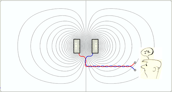
 Fig. 1
Inductance may come as a shock to anyone who thinks that V = I × R. That delightfully simple expression of Ohm’s law is not the whole story. For sure, if we have a coil connected to a battery, Ohm’s law will give the relationship between the voltage, the current, and the resistance of the coil. Approximately. In the steady-state. As long as the resistance and the battery voltage are constant. Etc. Etc. Etc.
But pull one of the wires until it breaks, and what happens? 1 Sparks! Of course electrical engineers don’t say ‘sparks’ : they say ‘arcs’ — the parting ends of the wire draw an arc. The anthropomorphic explanation is that the current wants to keep going even after the circuit is broken. But why? What keeps it going? The electrical engineer’s answer is inductance.
When we say ‘inductance may come as a shock’, it would be literally true if we were holding the ends of the broken circuit.2
What is inductance? The glib answer is that it is that which keeps the current going after the circuit is broken. This is true, but it is not terribly helpful for calculation. Engineers who design, manufacture, and instal switches and circuit-breakers may have this notion constantly in the forefront of their minds; but most of us are more concerned with the behaviour of electrical products when the current is flowing normally. In power-electronic circuits, when a circuit is broken by switching off a power-transistor, we don’t see arcs and we don’t even think about arcs: that’s because the current commutates into the respective freewheeling diodes and keeps going until some other event causes it to change. Without freewheeling diodes, power transistors could not function: as soon as they switch off, the circuit inductance will generate whatever voltage it needs to keep the current going, and that voltage is generally sufficient to blow a power transistor to smithereens. The art of power electronics is, to a large extent, the art of switching inductive currents safely — commutating them into alternative paths, not interrupting them abruptly. And that is all because of inductance.
Most of the time, when our motors and drive systems are working normally, we are interested in the design and performance with current flowing normally. Does inductance matter when the current is flowing normally, or only when the circuit is broken? Only in the simplest circuits do we find constant unidirectional current (DC), and only in those circuits can we forget about inductance (until something changes or the circuit is opened). In AC circuits inductance causes a voltage drop in addition to the voltage drop across the circuit resistance, and this voltage drop is often much larger than the resistive voltage drop, as every electrical power engineer knows.
Inductance did come as a shock to the early telegraph engineers in the mid-19th century, and it took the best brains in the industry to work out the complex effects of inductance on long-distance cable transmission, [1]. The principles were at first poorly understood and hotly debated, some asserting that inductance was uniformly evil, until Heaviside devised inductive loading and ‘sorted out’ the fundamental problems in the complex pattern of distortion, dissipation, and dispersion.
But aside from signal transmission along sub-sea telegraph cables, is inductance generally a good thing or a bad thing? What about electrical machines?
The answer is the answer that nobody wants to hear — it depends. A book could be written, but here we will simply borrow from [2] and list a few of the attributes of inductance that are important to electric machine designers. Here goes:
| 1 | In AC machines (including inverter-fed machines), inductance generally absorbs a fraction of the supply voltage, tending to limit the maximum speed that can be attained with any given level of current (and therefore also of torque). We could say that the inductance wastes precious volts. |
| 2 | Inductance affects the power-factor of AC motors and is closely associated with reactive power. These effects are manifested in phase shift of the current and a reduction in power per volt-ampere, both of which are observed also in brushless DC motors operating with squarewave currents. |
| 3 | The flux associated with the inductance (‘armature reaction’) is superimposed on the excitation flux of the magnets, and tends to distort it. When the magnetic circuit is nonlinear, this changes the torque constant (the torque per ampere). The flux contributions from different sources (such as permanent magnets and winding currents) cannot be simply added together when the magnetic circuit is nonlinear, because the principle of superposition becomes invalid (or, at best, weak and ambiguous). |
| 4 | In switchmode power-electronic circuits (including choppers and inverters), inductance determines the rate of rise and fall of current (di/dt) in the short intervals between switching events. Together with the EMF (if present), it determines the relationship between current ripple and chopping frequency. |
| 5 | During short-circuit faults the current is both limited and sustained by inductance, an important consideration in protective relaying and the use of overcurrent circuit-breakers. |
Machines that are intended to operate over a wide speed range present particular problems in relation to inductance. Low inductance ensures that most of the available drive voltage can be expended in overcoming the EMF, but motoring speed cannot then exceed the speed at which the EMF becomes equal to the available drive voltage. If the machine has sufficient inductance, the armature-reaction effect can be used to suppress the magnet flux to some degree, reducing the induced voltage and permitting the motor to run faster. This flux-weakening requires a controlled phase-shift in the current waveform, which may reduce the torque constant. In salient-pole machines like the IPM (interior permanent-magnet motor) the torque may be held up by the reluctance torque component, which depends on the difference between the synchronous inductances in the two axes of symmetry in the rotating reference frame fixed to the rotor. Flux-weakening and the management of reluctance torque is a complex topic that can suffer from ambiguities in inductance values (caused by saturation and the non-unique application of the principle of superposition), and it is one of the most complicated areas of inductance analysis in electric machines (though it is by no means the only one). This mode of operation is often associated with the search for a constant-power operating characteristic, rather than constant torque (versus speed).
Any detailed classical analysis of inductance seems to involve a great many components, [2,3]. Moreover, inductance is generally not constant, but varies with current and/or rotor position to a greater or lesser degree, depending on the details of the electromagnetic design. For example, the self-inductance of one phase of an AC machine can be considered to have at least three components: the airgap component, the slot-leakage component, and the end-turn component. Deeper analysis leads to the concept of harmonic or differential leakage inductance, which is difficult to visualize. The interaction of phases, rotor circuits, and rotation leads to the use of transformations such as the symmetrical-components transformation and the dq-axis transformation, both of which are foundations of space-vectors and field-oriented control. Specialized methods are needed to compute all these components, or to simulate machines with inductive properties.
Let’s finish by going back to the basic question, What is inductance? Nowadays my best answer to this is flux-linkage per ampere, ψ/i. This definition is useful in design calculations and fully compatible with the methods of both circuit analysis and field analysis using finite-element methods. Three important points can be added to this definition. One is that if the flux-linkage and the current belong to the same circuit, we have self inductance; but if they belong to different circuits, we have mutual inductance. The second point is that inductance in electric machines may vary widely with current and rotor position, and we must go into that deeply. The third point is that sometimes we need to distinguish between total inductance and incremental inductance: that is the difference between ψ/i and dψ/di. Magnetic saturation can make these differ widely from each other. The total inductance is used in the calculation of torque and terminal voltage in the phasor diagram, while the incremental inductance is used in calculating current ripple at the chopping frequency in a pulse-width-modulated inverter.
Inevitably someone will then ask, What is flux-linkage? and Where does time come into the picture? The answer is that flux-linkage is the time-integral of the induced voltage. In a simple static circuit it is the time integral of (v – Ri) where v is the terminal voltage and R is the resistance. This is Faraday’s law. In its differential form, induced voltage is the time-derivative of flux-linkage. Induced voltage is, in effect, the most common physical manifestation of magnetic flux in engineering. (One can argue that Hall-effect devices can detect flux under DC conditions, providing a manifestation of the existence of flux that is independent of Faraday’s law, and it’s an interesting question as to how to prove that this is the same magnetic flux that we observe through Faraday’s law. Similarly the force observed between current-carrying conductors, or between a current-carrying conductor and a ferromagnetic object, can be ‘explained’ with the help of flux and flux-density; but neither of these manifestations of flux involves inductance).
When we write L = ψ/i we imply that ψ = Li. Faraday’s law says that the induced voltage is dψ/dt, which we take to be universally true. This is equal to Ldi/dt + idL/dt, so that Ldi/dt is not the complete Faraday’s law unless L is constant (making dL/dt = 0). If L is varying (with current or rotor position or for any other reason), then we must include both terms when we calculate induced voltage. The calculation becomes complicated very quickly, and it often leads to confusion as to whether we should be using total inductance or incremental inductance. For this reason it is sometimes argued that the best way to calculate induced voltage is to use dψ/dt directly, and to calculate the relationship between ψ and i using the finite-element method without using inductance at all. For many years in my seminars I embellished this discussion with the whimsical slogan ‘abandon inductance!’, until a Brazilian colleague3 suggested we take it further, with the even more forceful slogan ‘abolish inductance!’
It has to be said that we never succeeded to abolish inductance! (Though we had much fun trying!)
1 Please don’t try this unless you know exactly what you are doing. Journalistic language in this article should never be interpreted as instructions or practical advice. Sorry for the disclaimer, but safety is paramount.
2 Don’t try it. This is strong advice, not ‘journalistic language’.
3 Prof. Aly Flores Filho, Federal University, Rio Grande do Sul
Further reading
[1] Nahin P.J. Oliver Heaviside, Sage in Solitude, IEEE Press, 1988 [2] J.R. Hendershot and T.J.E. Miller, Design of Brushless Permanent-Magnet Machines, 2010 (the ‘Green’ Book); sales@motordesignbooks.com See Chapter 5. [3] Grover F.W., Inductance Calculations, Van Nostrand, New York, 1946


