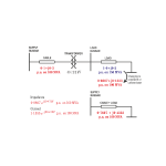
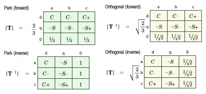
 Fig. 1 dq-axis transforms
In any system of calculations using dq-axis theory for synchronous machines, the question will arise, as to which transform should be used. 1 The two transforms shown in Fig. 1 are by no means the only ones, but they are both common and they certainly serve to bring the most important considerations into view.
These considerations are summarised in the following paragraphs in the form of questions and answers. Video 51 provides the mathematical basis by way of background. It also provides more detail on the conception and physical significance of the dq-axis transform, whereas this Engineer's Diary assumes that the reader already has a reasonable working knowledge (perhaps from using dq-axis models in computer-aided engineering calculations).
The first transform is the one published by R.H. Park in 1929 [1], and shown on the left-hand side of Fig. 1 in matrix form together with its inverse. The second, shown on the right-hand side, is an 'orthogonal' version that can be associated with W.A. Lewis [2]. The C and S terms are cosine and sine functions of the angular position of the rotor relative to the axis of phase a. These functions are extremely common in the literature, and they are the same in both transforms. Since they do not affect the main discussion, they are not written out here; (but see Video 51).
What's the difference between the Park transform and the orthogonal transform?
The orthogonal transform has the property that the inverse transform matrix is equal to the transpose of the forward transform matrix. This property is the definition of an orthogonal transform. It is evident that Park's transform is not orthogonal. We'll see why this is important, shortly.
Looking further at the details, we can see that Park's forward transform has a coefficient 2/3 and the inverse has no coefficient, while the orthogonal transform and its inverse both have the same coefficient √(2/3). Another (less important) difference can be seen in the zero-sequence elements in the rows and columns labelled '0'.
Can we use the same transform for voltage, current, and flux-linkage?
Yes! We should use the same transform for voltage, current, and flux-linkage. Otherwise we would have more to remember; errors would be more likely, and there would be a risk of chaos.
What is the meaning of the term 'power invariant'?
This term sounds as though it might have been invented specially to make engineers uncomfortable. But we have to deal with it.
If the same orthogonal transform is used for voltages and currents, the sum of the instantaneous voltage-current products will be the same in both the abc and dq0 frames of reference. The transformation is then said to be 'power-invariant'. 2 With the Park transform, the power in dq-axes must be multiplied by a factor 3/2 (and likewise the torque). The Park transform is not orthogonal and it is not power-invariant.
The 3/2 factor in the power and torque equations is repugnant to mathematical purists, and it may even be the main reason why some engineers prefer the orthogonal transform. But practical engineers may see it as a natural factor that arises in mapping the power from a 2-circuit model to a 3-circuit model, and this idea helps to remove any objection to the use of the Park transform. 3
In the case of wound-field synchronous machines, a non-orthogonal dq-axis transform leads to non-reciprocal mutual inductances between the field winding and the d-axis equivalent winding of the stator. Over the years, this has led to all manner of artifices to restore the reciprocity in these inductances, including the application of per-unit systems; [3,4]. It was the main reason why Lewis introduced the √(2/3) coefficient in place of Park's 2/3 coefficient, [2]. The reciprocity problem arises only with mutual inductances involving the field winding, so it does not arise in permanent-magnet machines.
Should we use a per-unit system when we use the dq-axis transformation?
No. For most machine designers today it is probably best to avoid the use of per-unit systems, and to work instead with actual or ordinary units.
At the time of R.H. Park (and others), beginning in the 1920s, difficult problems needed to be solved in calculating transients and faults in machines (mostly large machines) that were operating on AC power systems. There were no inverters! Per-unit systems were widely used, possibly to make the calculations more manageable, not only by slide-rule but (later) also with analogue computers and network analyzers which operated exclusively with normalized parameter values. Even though the problem of non-reciprocal mutual inductances could be resolved by means of a suitable per-unit system, there were serious conceptual difficulties in deciding what base values to use for normalization—so much so that many of the early publications (including [1] and [2]) are difficult to follow. The extent and depth of these difficulties are treated in [3].
Lewis himself, in spite of the fact that he was introducing an orthogonal transform that would resolve the problem of non-reciprocal mutuals, couched all his equations in per-unit, even while commenting that 'if equations are given only in per-unit form, . . . verification from physical reasoning is unreliable, and the checks provided by methods of dimensional analysis are not trustworthy', [2]. Looking back on all these original early works, it seems there was plenty of scope for confusion, which makes it all the more remarkable that practical complex calculation methods were developed and used so widely and effectively.
What is the relationship between dq-axis quantities and phase quantities?
With Park's transform, the peak phase current is equal to the magnitude of (id + jiq), or √(id2 + iq2). In design calculations or in the heat of laboratory testing (particularly of inverter-fed motors) this relationship is easy to remember. But with the orthogonal transform there is a coefficient √(2/3) = 0.8165 which must be remembered and applied every time the dq-axis currents are checked against the phase currents (and similarly with voltages and flux-linkages). This coefficient is a nuisance and it may make errors more likely. Unfortunately this awkward behaviour is rarely pointed out (but see [3]).
Does the form of the transform affect the values of Ld and Lq?
No — not if we restrict attention to the transforms of Fig. 1. This is proved in Video 51, and it is also crystal clear in Lewis [2]. It is not to say that other forms of the dq-axis transform will not produce different values of Ld and Lq. Beware! The last thing we need in electrical engineering is ambiguity in the values of such important inductances arising from a mere choice of mathematical convention.
The formulation of Ld and Lq is as important in measurement as it is in calculation. Methods for measuring these synchronous inductances are described in [8].
Why do we need the zero-sequence quantities?
Most of the time, in practical work, we don't need them. If the windings are star-connected with an isolated star point, the zero-sequence currents are zero, so they do not enter into any steady-state or transient calculations as long as this remains the case. However, if there is a ground fault or a connection to the star point of the winding, the zero-sequence quantities must be taken into account.
The reason why they always appear in the transform is mathematical. The transform matrix must be square, otherwise it cannot have a unique inverse. In processing the transform and its inverse back-and-forth, the zero-sequence terms can be seen as 'passengers' whose sole function is to preserve the rigour in the mathematics; but for most normal operating conditions, that is all they do. Both Park and Lewis defined their zero-sequence quantities using the same definition that is common in a non-orthogonal version of the symmetrical components transformation, but there is no a priori reason to do that. The orthogonal transformation in Fig. 1 differs from Lewis [2] in that detail.
Does the d-axis lead the q-axis, or is it the other way round?
The negative signs accompanying the S terms in Fig. 1 give a hint that the q-axis leads the d-axis. If positive signs were used, the q-axis quantities would change sign and the q-axis would lag the d-axis (by 90°). However, these statements are meaningful only in relation to the definitions of the positive directions of voltage, current, and rotation. A diagram is essential in support of these definitions; see Video 51 and [1-9].
The negative sign in the q-axis is also related to the relationship between real and imaginary components of the voltage and current phasors in steady-state operation, and whether the signs of these components are consistent with the signs of the cosine and sine coefficients obtained by Fourier series analysis of their time-waveforms. If you like to get lost in a thicket of algebra, this is a good place to start.
What is the relationship between dq-axis quantities and space-vectors?
The space vector represents a pair of dq-axis components (id, iq) as a single complex number. Space-vectors in field-oriented control theory are normally defined with a zero zero-sequence current, and this makes it possible to 'invert' a space-vector to recover the three phase currents uniquely, [9]. The debate over power invariance and the coefficient [2/3 or √(2/3)] arises in connection with space-vectors just as it does with the dq-axis transform. It is probably fair to say that the derivation of machine equations in space-vectors is more common in German literature, where it is closely tied to the field-oriented control of inverters. In the English technical literature there is a greater association with traditional power-system theory, as with Park [1] and (to a lesser extent) with Lewis [2]. That means that space-vector theory has to be grafted on to the classical dq-axis theory, whereas in the German literature the two are more integrated (especially for AC drives).
Shouldn't we be talking about Clarke-Park?
No. Edith Clarke — another distinguished GE engineer from the 1930s — is credited with the αβ0 transform of 3-phase (abc) quantities to 2-phase. It is sometimes used as a stepping-stone in the direction of a transformation into dq axes, possibly because the transform from αβ0 to dq0 is rather simpler than the Park transform. The Clarke transform itself is also simpler than the Park transform. It applies to static circuits and was developed for calculating unbalanced conditions; it is not a 'live' transformation and it does not remove the rotor-position dependency of the stator inductances; that's what Park does. Since abc to dq0 transforms are commonplace and straightforward, it can be argued that there is no need to 'disassemble' the process into separate stages abc to αβ0 to dq0 (although there may be pedagogic value in the eyes of some professors).
While this argument holds up for machine analysis per se, it turns out that the Clarke transform is equivalent to the transformation from abc axes to space-vectors. This is probably the reason why we often hear the term “Clarke-Park”. It suggests that analysis is being conducted in space vectors and in dq-axes at the same time.
Should we try to imagine the rotor as stationary and the armature rotating?
No. This idea was used in some older textbooks to help with visualisation of the rotational voltages (the speed voltages) in the so-called Park's equations (the voltage equations in the dq0 frame of reference). The idea was to think of the fictitious d- and q-axis windings as through they were connected through brushes to a commutator, in the days when commutator machines were common but inverter-fed AC machines did not exist. After all, the voltage generated at the brushes is a rotational voltage, isn't it? 4 They even used the term 'pseudo-stationary coils'. I remember as a student being thoroughly confused by these mental gymnastics. The dq-axis transform has everything we need. Keep it simple!
Where are Park's equations? Where is the diagram?
In the Green Book. In many books. See Video 51.
Recommendation
It is never perfectly safe to make a recommendation, but I will do it anyway. Perhaps the choice of a particular transform is less important than a full understanding of the chosen transform in relation to all the aspects discussed above (and any that might have been overlooked!) Documentation is also important: in any report, any article, any paper, or any calculating software, the choice of transform should be stated. It is not enough to say 'we use the power-invariant form': the transform matrix and its inverse should be declared in the form of a mathematical equation, and it should be confirmed that it is used for voltages, currents, and flux-linkages. Anything less leaves room for ambiguity and uncertainty.
My personal choice is the Park transform. In my early years I tried the orthogonal transform out of a sense of idealism, but I got into a tangle once when testing a 'hot project' in the lab., under the beady eyes of the technically astute management. 5 The 0.8165 factor (√(2/3) made me uneasy, and I did not have the mathematics to be sure that my values of Ld and Lq were the same as those used by others in the company, or anywhere else for that matter. The only complaint that might be levelled against the Park transform is the 3/2 coefficient in the torque equation; but I like to think that this coefficient has a physically meaningful engineering explanation, as discussed earlier, so I would say the complaint is superficial and does not stand up.
With Park's transform we are putting 100 years of engineering practicality above mathematical purity. It doesn't mean any sacrifice of rigour. Remember that Park and several of his contemporaries worked through the details at great length, and they were responsible for critical power-system calculations: they did not have the luxury of picking out a nice-looking transform from a textbook, but had to rely on the rigour of their own mathematics. It is true that Lewis with his power-invariant transform was expressing genuine engineering arguments, trying to resolve the knotty problem of non-reciprocal mutual inductances in wound-field machines 30 years after Park; but his transform was not fully orthogonal. Later literature is littered with transform declarations and special variants that are not accompanied by a proper discussion of all the consequences and important attributes. Many are incomplete and 'academic'.
For wound-field machines the Park Transform will have the reciprocity issue with mutual inductances involving the field winding. But this problem can be resolved by a simple change of variable (replacing the field current if by If = 3/2 if), as Lewis pointed out, and without the need for a per-unit system.
1 The term transformation is used here to refer to the general process of reference-frame transformation (meaning a change of coordinate system for the circuit equations of the machine). The term transform is used more narrowly to refer to the particular mathematical formulation.
2 It is also sometimes characterized as a tensor, but that is surely too sophisticated and too abstract for most engineering purposes. Note that Lewis' transform [2] was not completely power-invariant because of his choice of coefficients for the zero-sequence quantities; this choice was made to be consistent with a common (non-orthogonal) form of the symmetrical components transform.
3 This sweeping statement implies certain assumptions about the effective numbers of turns in the d- and q-axis 'coils', relative to those of the phases.
4 The voltage at the brushes in the commutator machine includes both 'speed voltages' and 'transformer voltages' — just as in Park's equations!
5 Incidentally, this was in the same works where Park worked in the 1920s and Edith Clarke in the 1930s, and Steinmetz a generation earlier. Hallowed ground!
References and further reading
[1] R.H. Park, Two-Reaction Theory of Synchronous Machines, Transactions A.I.E.E., pp. 718-727, 1929.
[2] W.A. Lewis, A Basic Analysis of Synchronous Machines — Pt. I, Transactions A.I.E.E., Vol. 77, pp. 436-456, 1958.
[3] Harris M.R., Stephenson J.M. and Lawrenson P.J., Per Unit Systems, Cambridge University Press., 1970.
[4] Concordia C., Synchronous Machines, John Wiley & Son, 1951.
[5] Fitzgerald A.E. and Kingsley C., Electric Machinery, 2nd edition, McGraw-Hill, 1961.
[6] Kimbark, E.W., Power System Stability; Vol. III Synchronous Machines, IEEE Press, ISBN 0-7803-1135-3, 1995.
[7] Kron G., Tensors for Circuits, Dover Publications, New York, 1959.
[8] J.R. Hendershot & T.J.E. Miller, Design of Brushless Permanent-Magnet Machines, Motor Design Books LLC, 2022, sales@motordesignbooks.com ISBN 978-0-9840687-0-8.
[9] J.R. Hendershot & T.J.E. Miller, Design Studies in Electric Machines, Motor Design Books LLC, 2022, sales@motordesignbooks.com ISBN 978-0-9840687-4-6.

