CWIEME, known to be one of the world’s largest exhibitions, gather products related to coils such as winding machines, motor stators and insulating paper.
At the JMAG booth we will introduce the latest technology on electromagnetic field analyses and demonstrate applied cases for motors, generators, and power transformers.
This will also include a demonstration of JMAG-Designer Ver.15.1, which is scheduled to be released in June of this year. We look forward to seeing you there.
CWIEME Seminars
A presentation on the latest electromechanical designs will be held by Ms. SIGRID JACOBS from ArcelorMittal, a JMAG partner.
JMAG will also be introduced at the presentation. Please come join us!
| When | 16:30 – 17:00, 10 May 2016 |
|---|---|
| Where | CWIEME Central |
| Details | https://berlin.cwiemeevents.com/home |
The latest trends in technical assistance to speed up and optimize the development of the electrical machines
SIGRID JACOBS
Portfolio Director, Electrical Steel, Global R&D, ArcelorMittal
Main Exhibition
Overview
| Date | Tuesday May 10 – Thursday May 12, 2016 |
|---|---|
| Venue | Messe Berlin South Entrance (Berlin, Germany) |
| Booth No | Hall 1-1 #11D10
|
| Host | i2i Events Group |
| URL | https://berlin.cwiemeevents.com/home |
Exhibition
Computing Large Numbers of Cases
JMAG’s new functions for computing very large numbers of cases, our current state of support for cloud and cluster systems for even faster processing, and case studies will be discussed.
The all-new “Power Simulation License”, which drastically cuts license costs for computing large numbers of cases, will also be announced.
Daily pickup: “HPC for High Precision Efficiency Map”
Daily pickup: “Efficiency Map Calculation Using a 3D Model”
Optimization Calculations
In JMAG, optimization can be performed accounting for the many conditions and trade-offs required for motor design, such as magnetism, electricity, heat, intensity, and vibration.
Please see JMAG’s new optimization functions and case studies.
Daily pickup: “Case Study of Multi-objective Optimization for Motor Design”
Large-Scale Computations

To meet these demands, we have been working aggressively to develop a fast solver; with that said, we are ready to release a new massive parallel (MPP) solver.
The high scalability of this new MPP solver allows the newest HPC systems to achieve their peak performance, making models with over 10 million elements solvable in a realistic time frame. Of course, the MPP is also highly scalable for models with a million elements that are commonly used today.
JMAG’s new MPP solver and high speed processing technologies will be discussed.
Material/Loss Modelling
To solve this issue, we developed an analysis function accounting for the effects of residual strain.
Degradation properties due to processing are identified with general single sheet tests.
The tool has made it easier in defining degradation regions and assigning properties.
Now we will explain JMAG’s high-fidelity material modelling technology.
Daily pickup: “Loss Analysis including Effect of Manufacturing Degradation Due to Punching (Materials Measurement)”
Daily pickup: “Loss Analysis including Effect of Manufacturing Degradation Due to Punching (Analysis)”
Multiphysics
Not only is it abundant in analysis functions, it also supports various applications. In addition to multiphysics analysis of JMAG, it also supports cooperative analyses with users of third-party products.
Our latest package has enhanced the direct interface with Abaqus, STAR-CCM+, and NASTRAN. New case studies will be introduced with analysis procedures and demonstrations.
Daily pickup: “Multi-objective Optimization Based on Multiphysics Analysis”
In a Transformer
On the other hand, it is difficult to directly verify many phenomena that affect safety occurring inside the transformer because of the size and the high voltage.
JMAG does not only simulate the physical phenomena occurring inside the transformer, but also visualizes ?the critical aspects to be improved.
Technology Conference

Topics covered will, of course, include the implementation of JMAG as well as covering the problems of analyses in motor designs.
JMAG-Designer Ver.15.1 Release

Numerous further additions and improvements have been made in the latest version, including the enhanced scalability of our massive parallel (MPP) solver and automatic generation function of detailed wire models.
At the JMAG booth, you can try these latest features before they are released anywhere else!
Daily Pickup
We obtained the Pareto optimum solution by including stress on the bridge part at maximum rotation speed as the constraint condition for multi-objective optimization that set average torque maximization and magnet volume minimization as the evaluation function. Torque obtained from magnetic field analysis and stress obtained from structural analysis were evaluated at the same time.
Fig. 1 Designs with stress distribution for a Pareto optimum solution.
The gray figure on the left shows the geometry information of the magnet and flux barrier used as design variables of the multi-objective optimization.
The three contour plots on the right show the Mises stress distribution when maximum rotation speed of 5500 rpm is applied to each design proposal. The upper right is the design proposal for maximum torque; the bottom left is the design proposal for when the magnet is minimized. The center design proposal shows a balance of both.
Fig. 2 Changes in the Pareto optimum solution due to stress.
The black dotted line shows a Pareto optimum solution with average torque and magnet volume as the objective function. The red dotted line shows a Pareto optimum solution with stress added as a constraint condition.
2016-05-10
There is a trade-off relationship between the maximization of average torque and minimization of magnet volume. One solution is to enlarge a magnet to produce large torque; however, another solution is to minimize volume as rare earth high-output magnets are expensive.
We conducted evaluations of average torque maximization and magnet volume minimization using multi-objective optimization with genetic algorithms (GA) in order to obtain a Pareto optimum solution. The curve connecting to the red dot in Figure 1 is the Pareto optimal solution. Figure 2 shows three model cases from the original geometry and the Pareto optimum solution.
Figure 1 shows trade-offs of the Pareto optimum solution
Figure 2 shows motor design cases with the Pareto optimum solution
2016-05-09
With the finite element model, the degraded region is split into multiple layers and degradation characteristics, according to the distance to the cross-section, will be applied.
The above may seem like it would be time-consuming manual work, but it is all done automatically by the software.
This has made it possible to make comparisons of the degraded and non-degraded case.
At the venue on the day of our session, we would like to present topics such as loss analysis and material modeling.
Layered degradation region in analysis model
Comparison of Hysteresis loss density distribution
Hysteresis loss density along the cutting edge is larger than
the one of the case that the steel sheets are not punched.
2016-04-28
Although there are ways to assess the particulars of strain distribution, here we will examine ways to identify degradation characteristics using commonly used material measurements.
Using this method, the degradation characteristics are presented as a function of the distance from cutting edge.
The identification of function parameters is conducted using the data from the single sheet testing with different sheet width we can see from the graph that relative permeability decreases as the cross-section gets closer.
Identification of the degradation characteristics in common single sheet testing is the point of this method. On the day of the session, a more detailed explanation will be given at our venue.
Identify the degradation distribution of the relative permeability in the lamination steel sheet
2016-04-27
As with the previous example, approximately 2500 operating points were used in a 3D model to perform calculations in the efficiency map below.
Efficiency map using a 2D model
Efficiency map using a 3D model
The efficiency map was calculated in approximately two days by simultaneously running multiple jobs on the Amazon Web Services (AWS) cloud.
We can see by comparison of the two maps that there usually is no difference between the maximum torque lines; however, after field weakening controls occur at higher RPMs, torque differences can be seen. Due to magnetic saturation, magnetic flux flows out in a 3D way and, in turn, mitigates magnetic saturation. Not only efficiency but various types of performance loss, currents at each operating point, and details such as inductance values can be found at the booth on the day of the session.
2016-04-25
The below is an example of an efficiency map calculation based on a 2D finite element model with approximately 2500 operating points.
(Hover image to enlarge)
For the contour line of the N-T curve, vector control accounting for the non-linear inductance, voltage limit, and current limit are performed. In this efficiency map, 7 jobs were run simultaneously taking approximately 2 hours to complete calculations.
Case calculations utilizing cluster environments such as HPC will also be presented at our booth.
Next, I would like to introduce the same calculations as above utilizing a 3D finite element model.
2016-04-22
Event Report
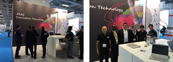
JMAG was exhibited at CWIEME (the largest coil-winding exhibition in the world) where a multitude of coil-related products such as winding machines, motor stators, and insulating papers were gathered for display.
This year, due to many of the planned motor related speeches, there was a greater number of motor and generator related attendees than in average years of the past.
Also at the JMAG booth, a giant wall illustration of motor analysis greeted the attendees. A partner agreement was concluded with Arcelor Mittal, a world-leading steelmaker, and materials characteristics were installed into JMAG. They also kindly introduced JMAG in their speech and exhibited the JMAG case studies at their booth.
Many people from businesses around the world such as Europe, America, China, and Korea visited the JMAG booth; we were very impressed by the turnout.
Contact
JSOL Corporation
Engineering Business Division
info@jmag-international.com

