Is FEA effective in motor design?
This issue is aimed at those designing or using motors, we let you know the effects of utilizing simulations. We would be happy if this is used as a reference for designing better motors.
Overview
Along with the progress in computers and software, finite element magnetic field analysis (FEA below) is being utilized in motor design and is actually producing results in development. On the other hand those not using FEA might be thinking, “I know FEA is good but evaluating will take effort and time so in the end a traditional design sheet will be quicker.” In this series, we will explain “Why FEA is effective in motor design?”. We would be happy if this is used as a reference for utilizing FEA and designing better motors.
FEA’s Benefits
In the motor design field, the benefits of using FEA are gathered below and compared with using the magnetic circuit method which has often traditionally been used.
- Motor geometry can be expressed in detail
- Magnetic saturation can be handled precisely
- Complex phenomena can be visualized
- Motor geometry can be expressed in detail
In FEA, motor geometry is expressed as it actually is with finite element mesh so it is possible to obtain an answer regardless of what the motor geometry is like. In contrast, in the magnetic circuit method it is necessary in advance to assume places magnetic flux will pass through as flux paths. Flux paths that were not assumed can be regarded as not existing. On this point FEA is extremely effective in evaluating motors with complex flux paths and new types of motors in which we do not know how to assume flux paths. - Magnetic saturation can be handled precisely
The magnetic circuit method can also to a certain degree account for the effects of magnetic saturation if nonlinear permeability is applied to the flux paths. However as magnetic saturation grows stronger, even inside the flux paths permeability distribution arises and handling it becomes difficult. In addition, when magnetic saturation grows stronger, magnetic flux is leaks from the flux paths assumed and in order to handle this phenomenon, it is necessary to identify the flux paths where flux is leaking and which route was taken. In contrast, FEA can account for permeability distribution and leakage into the air and deal precisely with magnetic saturation. From this point, FEA can be said to be particularly essential in the design of recent permanent magnet synchronous motors using rare earth sintered magnets which have extremely strong magnetic force. - Complex phenomena can be visualized
This could be said to be FEA’s biggest benefit. The motor design’s good and bad points can be understood from the motor design results and from looking at the acquired macro amount for torque and inductance but what is really important is understanding, “Why is it this way?”. If this is not understood, we cannot make better designs. With FEA it is possible to visualize magnetic flux distribution inside the motor which would be extremely difficult to actually measure. Doing this allows us to understand local magnetic saturation and to put this to work understanding causes and measures. Also by visualizing not just magnetic flux but also eddy currents and demagnetization of the magnet, it is possible to have a motor design with higher efficiency and reliability.
Utilizing FEA at Each Phase of the Design
Here for convenience we will divide motor design phases into three, “concept design, initial design”, “detailed design”, “perfecting the design” and we will explain how FEA’s benefits can be put to work in each phase through a series in three parts, starting from this issue.
- Concept design, initial design stage
At this stage we calculate motor properties and decide a rough layout, size, number of poles and number of slots. In this first issue, we will introduce ways to utilize FEA in concept design, initial design stages. - Detailed design stage
At this stage, we take the rough design decided in the concept design, initial design stage and perform a parameter study assigning parameters such as dimensions and current value for each part of the design and we optimize the design. In the second issue, we plan to introduce optimization using FEA and also ways to analyze FEA results and use them as knowledge in the design. - Perfecting the design
FEA is effective when taking the design refined in the detailed design stage and perfecting it more, when performance from actual machine experiments is below that forecasted and for analyzing cause when troubles arise. For example, eddy currents generated in permanent magnet motors, demagnetization, effects of stress in magnetic steel sheets, effects of inter-bar current in induction motors are areas in which FEA’s high analysis abilities are demonstrated and we plan to introduce actual examples in the third issue.
Permanent Magnet Synchronous Motor Initial Design
Permanent magnet synchronous motors are used in fields such as power trains of hybrid, electric vehicles and in air conditioners or washing machines so there are expected to have high performance and high efficiency. Because they use rare earth sintered magnets with high magnetic force and are expected to have high output density, one of their characteristics is that the magnetic flux distribution in the iron core tends to be high.
Here we will see how FEA can be utilized in the initial design stage of permanent magnet synchronous motor designs.
Characteristics of interior permanent magnet synchronous motors
Recently, among permanent magnet synchronous motors, there are an increasing number of examples of adopting interior permanent magnets types (IPM below), which make possible reluctance torque combined usage. IPM enable reluctance torque and magnet torque in the current phase to be controlled so they realize enhanced efficiency in wide drive ranges. However, IPM also has a higher level of rotor design freedom than traditional surface magnet types and because flux paths in the motor also change depending on current controls, it is difficult to apply the traditional magnetic circuit method to them. By applying some restraints, it is possible to use the traditional magnetic circuit method but there end up being restraints applied to the level of freedom. In contrast, FEA has no restraints so it is possible to freely test rotor designs that have not been tested before. FEA utilization can also be said to be essential in the initial design stage when the rough motor layout is decided for motors which have a high level of freedom such as IPM.
Evaluating the magnet layout
Using JMAG-Express, which is a tool enabling the effects of FEA to be experienced easily, we will test an IPM with three magnets in each pole and placed in a triangular arrangement, as shown in Fig. 1. When using a magnet arrangement like this that we have no experience designing, how much are the dq axis inductance which is important to decide the character of the IPM? The results of the characteristics calculated are shown in Fig. 2. JMAG-Express is using FEA but these results could be derived in under one second.
In this way, d axis inductance Ld is12.7mH, q axis inductance Lq is 32.2mH, with regard to how much reluctance torque can be obtained, we discover instantaneously how far we might be able to raise the revolution speed in the voltage supplied to the inverter. By also easily testing layouts other than this, we get an indication of what kind of layout we should use to achieve the design objectives.
After this we will use JMAG-Designer to, decide the magnet angle and implant depth, run a parameter study of flux barrier geometry, and carry out design optimization.
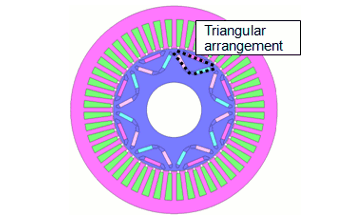 Fig. 1 Motor with magnets in triangular arrangement
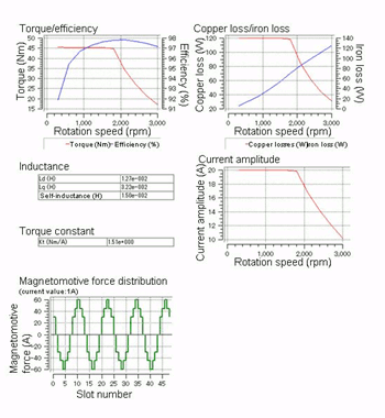 Fig. 2 Motor characteristics with magnets in triangular arrangement
Induction Motor Initial Design
Induction motors have been used in a wide range of fields since until now but they are receiving new attention as efficiency regulations are introduced and as an alternative to permanent magnet motors as rare earth prices rise. Here we will look at how FEA can be utilized in the initial design stage of induction motors.
T-shaped equivalent circuit in induction motors
In initial design of induction motors, calculations of torque and current characteristics in relation to slip are performed often using the T-shaped equivalent circuit shown in Fig. 3. The leakage reactance and secondary resistance used in the T-shaped equivalent circuit (equivalent circuit parameter below), are important parameters for deciding induction motor characteristics and in design when the rotor is locked or in no-load rotation, the equivalent circuit parameter is estimated from the magnetic circuit method and the cage geometry.
For induction motors with deep-slot cages such as the one in Fig. 4, an equivalent circuit parameter is obtained when the rotor is locked and in no-load rotation, torque-slip characteristics were obtained from the T-shaped equivalent circuit and the results are shown in Fig. 5. Fig. 5 shows the results of a detailed FEA analysis that was carried out after and in calculations by the T-shaped equivalent circuit, maximum torque is overestimated as much as 60% and we understand that slip that becomes maximum torque is also different. Why do the results end up like this?
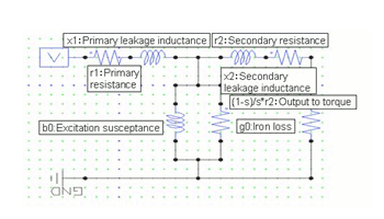 Fig. 3 Induction motor T-shaped equivalent circuit
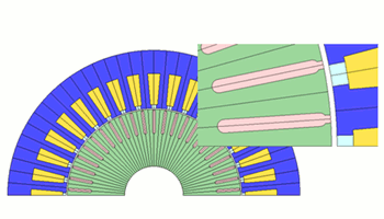 Fig. 4 Deep-slot type induction motor
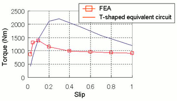 Fig. 5 Slip characteristics comparison 1
Equivalent circuit parameter calculations using FEA
In order to examine the causes, the current distribution for the bar of slip 1 (when locked), and slip 0.5 is shown in Fig. 6. Both have the same contour range. In contrast to slip 0.5 in which the current has permeated to the inside of the bar and the distribution is comparatively uniform, we understand from slip 1 that it has accumulated near the slot opening. This phenomenon is caused by slip changing the frequency of the magnetic flux linkage in the rotor. Secondary resistance differs greatly depending on whether the current has distribution or is uniform (the greater the current accumulation, the greater the secondary resistance), we can infer that the reason characteristics in Fig. 5 did not match is “because the secondary resistance obtained when bound was used for another slip”. Also because current distribution changes, we can forecast from the contour diagram that leakage flux is affected.
 (a) Slip 1
 (b) Slip 0.5
Fig. 6 Bar’s current distribution
Using FEA in this way in detailed analysis enables the slip characteristics that account for current distribution in bars to be obtained but on the other hand, calculation takes time. That’s why we think about utilizing FEA in equivalent circuit parameter calculations. As shown in the example before, for slip 0.5 and slip 1 we calculate the equivalent circuit parameter and use it in T-shaped equivalent circuit calculations (for other slip, obtain equivalent circuit parameter with linear interpolation and extrapolation). Slip-torque characteristics that will obtain results are shown in Fig. 7. By comparing it with Fig. 5, we can understand there is a major improvement in accuracy. Detailed analysis with FEA certainly does takes calculation time but calculation time using FEA to calculate the equivalent circuit parameter introduced this time is over in a few minutes.
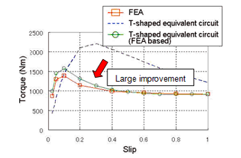 Fig. 7 Slip characteristics comparison 2
Here we introduced that by utilizing FEA in the initial design stage, it is possible to forecast induction motor characteristics that are highly accurate. The bar we used this time had simple geometry but in the case of a bar with complex geometry which we have not experienced design before, because of our lack of knowledge it would be difficult to estimate the equivalent circuit parameter, so FEA would be even more effective in estimating the equivalent circuit parameter.
In Conclusion
- Interior permanent magnet synchronous motor design has a high level of freedom and FEA utilization is essential to ensure restrictions are not placed on the level of freedom of the design.
- At the initial stage of the design of induction motors, characteristics are calculated using an equivalent circuit but by using FEA to estimate equivalent circuit parameters that account for current distribution, it is possible to greatly improve the accuracy of the calculations.
(Katsuyuki Narita)
[JMAG Newsletter January, 2013]

