Is FEA Effective in Motor Design?
This issue is aimed at those designing or using motors, to let you know the effectiveness of utilizing simulation. We hope you will find this useful as a reference for designing better motors.
Overview
As computer hardware and software becomes more advanced, finite element method electromagnetic field analysis (hereafter FEA) is being used more, and its real effectiveness in development facilities is growing.
However, if you talk to people who are not using FEA now, there are many who say things like "I've heard that FEA is good, but we can accomplish the same things with our current development process, so we don't need it," or "It seems like it would take a lot of time and effort to adopt it."
This series attempts to respond to the concern of "why is FEA effective in motor design?" We hope this helps you to understand the benefits of using FEA for better motor design.
In Issue 1, I discussed the use of FEA at the concept design and initial design stages in motor design. Here in Issue 2, I will present uses for FEA at the detailed design stage. The goal at this stage is to optimize design variables based on rough proposals determined at the concept and initial design stages, and then to settle on design parameters such as measurements, conditions, and material properties for the various parts. We will discuss effective use of FEM in design optimization at the detailed design stage, and how to analyze FEA results and apply them to designs.
Improved Performance and Development Issues in PM Motors
The following is an outline of the difficulties in improving performance in detailed design, not limited to motors.
1: Balancing trade-offs to find optimal values
There is a wide range of issues to solve in order to improve motor performance. Many of these have trade-off relationships with others, such as reducing iron loss to improve efficiency and reducing torque variation so it will not cause vibration, so when one is prioritized, others are hindered, and finding the proper balance is never easy (Fig. 1). For example, magnet volume can be increased to improve output density, but this makes cost reduction more difficult. In order to choose the best values among these complicated trade-off relationships, designers must have quantitative knowledge of the relationships between solutions to the various problems, and FEA that encompasses the physical phenomena is vital for this.
 Fig. 1 Improved performance and development issues in motors
2: Pushing it to the limit
Motors are already quite efficient compared to other energy-conversion devices. Improving this efficiency even further is the goal, so efforts must be made to poke into every little corner in order to reduce loss. FEA is unrivalled for the sort of minute test studies needed for this purpose.
3: The need to draw out new abilities
If all issues could be solved by extension of the design techniques used in the past, then veteran designers would be able to produce design proposals using magnetic circuit methods, etc., based on their experience without using FEA. However, it becomes necessary to jump up to a new level over past experience in order to push optimization of trade-offs all the way to the limit. In cases like these, it is extremely hard to accomplish only by extrapolating past experience, but with FEA, even unconventional ideas that would give pause for prototyping can be tried out.
Creating Performance in Detailed Design
Models can be made precisely and even nonlinear magnetization properties for materials can be accurately modeled in FEA, so the complex electromagnetic phenomena occurring inside a motor can be reproduced. Designers' ideas can be brought to life and evaluated right on the desktop, allowing better design proposals to be advanced. Below is an explanation of the benefits of FEA, including concrete examples.
Reduction of Cogging Torque
For example, there are times when you may want to reduce cogging torque in a high-end motor. Cogging torque is highly sensitive to details of a motor's geometry and is also affected by material properties, so it poses a difficult design theme.
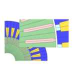
It is well-known that one solution to reduce cogging torque is to add skew to the rotor or stator, but because this has demerits such as a fall in productivity, reduction in torque coefficient, forces generated in the slant direction, etc., designers are instead expected to reduce cogging torque by optimizing magnetic circuit geometry rather than adding skew. Although it is easy to talk about optimizing magnetic circuits, the parameters are in fact quite complex. A main cause of cogging torque is intermittent changes in magnetic resistance in the stator due to the coil slots, so it can be reduced by appropriately designing the pole arc angle of the magnets and the slot pitch. Figures 2 and 3 show a study of variations in pole arc angle with the design parameter of magnet width in an SPM motor. In this study, with magnet width varied from 14 mm to 11 mm, minimization occurs at 12.5 mm, being about half compared to the initial value of 14 mm. However, if magnet width is made any thinner than this, cogging torque starts to increase, and is much higher at 11 mm even than at the initial value.
 Fig. 2 SPM motor geometry
 Fig. 3 Differences in cogging torque due to magnet width
In an actual motor, the magnets' corners are given an angle R in order to prevent magnet breakdown and peeling of the magnets' surface treatment. For the magnetic circuit, this makes switching at the boundary more lenient, so it can be expected to have an effect on cogging torque reduction as well. A study is conducted on this model with magnet angle R varied from 0.25R to 1.5R, with 1.0R showing minimized values (Figures 4 and 5).
 Fig. 4 Differences in magnet angle R geometry
 Fig. 5 Differences in cogging torque due to magnet angle R
FEM shows its true power in studies such as this kind of reduction of cogging torque. Only cogging torque reduction has been focused on here, but it can also help to determine geometry by evaluating the motor's induced voltage waveform and torque coefficient in parallel. Cogging torque analysis is a comparatively advanced-level use of FEA, so it is necessary to take adequate care of the modeling process, such as the symmetry of the mesh.
Optimized Design of the Rotor's Magnetic Circuit
Optimal use of material properties and efficiency in magnetic circuit design are called for to meet demands for smaller and lighter motors. If designs are made to allow some leeway in terms of magnetic saturation in the materials, it is possible to avoid a reduction in controllability due to increased iron loss and nonlinearity, but this leads to an increase in motor size. On the other hand, not providing this leeway means a reduction in the torque coefficient, higher loss, and worse controllability due to materials strain. For this reason, it is necessary to properly grasp the degree of magnetic saturation in order to design magnetic circuits that are not wasteful and not overloaded. This can be evaluated to a certain degree using the magnetic circuit method, but FEA is indispensable for designing to the limit. In particular, the magnetic circuit around the magnets in an IPM motor's rotor is extremely delicate, and has a large effect on the torque coefficient, iron loss, and torque variation.
Professor Yamazaki of Chiba Institute of Technology presented his results from optimized design of an IPM motor in his keynote address at the 2012 JMAG Users Conference (although unfortunately the study results used FEA developed by Professor Yamazaki himself). An improvement in performance was achieved by creating an appropriate slit near the rotor's air gap, but because in practice this type of measure means an increase in the length of the air gap and thus an increase in magnetic resistance, common sense seems to tell us that this should not contribute to an increase in motor performance. In fact, however, because the flow of the magnetic flux in the rotor became more ordered, iron loss was reduced thanks to suppression of higher-order components, and it was shown that the overall performance and efficiency of the motor was improved. In the future, it seems likely that this type of thinking about proper control of the magnetic flux flowing in the magnetic circuit will become more widespread. This sort of idea is made possible thanks to the use of FEA.
Yamazaki Katsumi, Chiba Institute of Technology, "Loss analysis and shape optimization of rotating machines," presentation materials from JMAG Users Conference 2012.
Appropriate Magnet Geometry Design計
It goes without saying these days that the rare earth magnets used in rare earth magnet motors are expensive. For this reason, designers want to get the maximum performance while using the minimum amount of them. Furthermore, these magnets are very delicate materials that are particularly susceptible to reduced magnetic properties due to raised temperatures, so adequate care must be taken of their useful temperature range so that they do not undergo thermal demagnetization. Also, field weakening controls are used to widen motors' output range, but since these weaken their field, there is great danger of demagnetization. Because it is difficult to restore a magnet's properties once it has undergone irreversible demagnetization, it is necessary to anticipate the surrounding temperature and tolerance for overloading in order to prevent demagnetization.
The following is an example of how motor characteristics change with variations in magnet width in an IPM motor. With the magnet thickness increased from 2.5 mm to 4 mm, attention is given to no-load induced voltage, torque, and the average magnetic flux density of the magnets (Fig. 6). An increase in thickness from 2.5 mm to 4 mm means a 60% increase in magnet volume, but induced voltage only sees an 8.3% increase. However, torque is increased 15.4%, with confirmation of this torque increase due to an armature reaction resisting the reverse magnetic field when the magnet is made thicker. Further, the average magnetic flux density for the whole magnet increases 23.8%, from 0.52 T to 0.65 T (Fig. 7). These results tell us that the risk of demagnetization from heat and reverse magnetic field is reduced because the magnets' operating permeance is higher. This is to say, torque may not be much reduced with a reduction in magnet volume, but the risk of demagnetization becomes much higher.
 Fig. 6 Motor model used for magnet thickness study
 Fig. 7 Effects of properties due to magnet thickness
Neodymium sintered magnets are notorious for having relatively high electric conductivity, leading to eddy currents produced by slot harmonics and carrier harmonics that can cause heat generation, and therefore a rise in magnet temperature. As a workaround, divisions are often made in the magnets with insulating material in between, similar to the concept behind laminated cores. However, as the number of divisions increases, production costs rise and magnetic properties fall, so it is important to design with the right number of divisions. The rotor and stator geometries strongly affect harmonic components, so a lot of factors have to be taken into account in order to determine the number of divisions. The number of magnet divisions and reductions in eddy currents are shown below (Figures 8 and 9).
 Fig. 8 Motor model used for magnet eddy current loss study
 Fig. 9 Reduction in eddy current loss due to magnet division
Maintaining Revolution Strength
Higher revolutions are essential for higher motor output. In terms of mechanical strength, rare earth sintered magnets are hard and brittle, so there is a danger of rupture if centrifugal force acts on them locally due to high-speed revolution. When the SPM motor in Figures 10 and 11 rotates at 10,000 rpm, the stress concentration generated in the magnet by centrifugal force is as shown. This model's structure has the core holding the corners of the magnet, and around 500 MPa of stress is produced in places. Since the compressive stress of rare earth magnets is supposed to be 1000 MPa, it can be seen that it has a safety factor of only 2.
 Fig. 10 Rotor model geometry for the SPM motor
 Fig. 11 Stress concentration generated in magnet during rotation
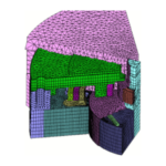
In IPM motors, where the magnets are embedded inside the rotor, the bridge part of the core supports the magnets' centrifugal force, and so concentrates the load in itself. From the standpoint of the magnetic circuit, it is better to design the bridge thinner to suppress leakage flux in the rotor, but if it is made too thin, it becomes unable to withstand the centrifugal force. Therefore, it is necessary to achieve a geometry that satisfies the needs of both the magnetic circuit and mechanical strength. To investigate these, the magnetic circuit is evaluated with magnetic field analysis, and the rotational mechanical strength is evaluated using structural analysis. The stress distributions produced in an IPM motor's bridge are shown in Figures 12 and 13.
 Fig. 12 Rotor model geometry for the IPM motor
 Fig. 13 Stress concentration generated in bridge area during rotation
Adjusting Output Characteristics
The proportion of iron loss within total loss increases with higher rotation in motors, and high-output motors can have equal amounts of copper loss and iron loss. How to control iron loss is a major issue in motor design when it comes to improving efficiency. Iron loss can be reduced by lowering the operational magnetic flux density using magnetic pathways with some leeway or by using materials with lower iron loss, but these lead to larger motor size and higher cost, and so cannot be adopted easily.
Because of this, what designers apply themselves to is seeking versatile designs that maintain the necessary maximum torque while keeping a high-level balance between cost, size, and output. They do this by focusing on high efficiency over the entire range, realizing high efficiency in output range over longer operating times while ignoring efficiency in output range for shorter operating times.
The example in Fig. 14 uses efficiency maps to show the difference in output characteristics when magnets in the same stamped motor geometry are replaced with a Br1.0 T material from a Br1.2 T material, and the difference is made up for by changing the number of turns in the coils to maintain the same torque coefficient. There is no difference in maximum torque before and after the replacement because the torque coefficient is the same, but because of increased iron loss, the torque at 3000 rpm is reduced from 2.6 N" m to 2.1 N" m, meaning a large decrease in output. Similarly, the torque at 6000 rpm goes down from 1.5 N" m to 1.0 N" m. Still, this could be recommended in situations where a reduction in magnetic properties to lower costs is prioritized, because overall efficiency is realized at more than 90% over a wide range in both cases.
 Fig. 14 Differences in output characteristics and efficiency
(Left: efficiency map of magnet Br1.2(T); Right: efficiency map of magnet Br1.0(T))
Reducing Torque Variation
Torque variation, a cause of vibration and noise in motors, needs to be reduced in order to improve performance and quality. Torque variation is influenced not only by the motor's structure, but also by the phase current waveform, so analysis using FEA is essential.
Adding high harmonic components to the flowing current changes the torque waveform. Figures 11 and 12 show results from analysis of torque variation when the drive is by a sinusoidal-wave current and when third-order current has been added. It can be seen that there is a difference in the torque waveform when a third-order component of 0.5 A is superimposed and when 1.0 A is superimposed onto the fundamental 5 A wave. In this study, the torque variation was not reduced to zero, but it is possible to suppress a current waveform to zero by adjusting the amplitude and phase of each superimposed order.
 Fig. 15 Phase current waveform with superimposed 3rd order harmonic
 Fig. 16 Changes in torque variation due to flowing current
In Conclusion
Issue 2 of "Is FEA Effective in Motor Design?" has presented example uses for FEA during detailed design. The examples here have focused on evaluation issues for permanent magnet motors, but these apply similarly to inductance motors and SR motors.
I hope you have come to understand just how valuable using FEA can be for detailed motor design. It is nearly impossible to carry out this kind of study using only calculation by hand and experience.
Of course, I do not mean to say that just using FEA guarantees good design. Engineers who have never designed a motor, however well versed they are in how to operate FEA, will not be able to apply the results to their designs. What I hope you will take away from this is that engineers who are already familiar with motor design will be able to put FEA to use in creating even better designs.
In the next issue in this series, I plan to explain how even more detailed motor design can be accomplished using FEA. In particular, I will present how to take advantage of its potential to find the cause when problems arise in a real motor.
(Yoshiyuki Sakashita)
[JMAG Newsletter March, 2013]