 Fig. 1
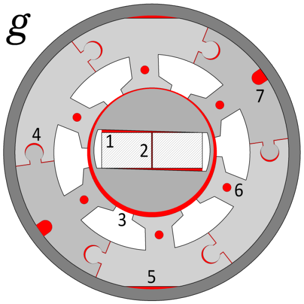
Fig. 1 shows a 2-pole IPM (interior permanent-magnet motor) that nobody would want to build. It has so many ‘departures from the ideal’, yet all of its imperfections can arise in real products to a greater or lesser degree. When we do our design studies using idealised perfect models, we are to some extent hiding from the realities that can cause trouble in the product, even after many thousands have been produced.
Let’s consider some of these imperfections in detail. Fig. 2 shows the open-circuit flux-plot calculated in JMAG with a mesh of some 590,000 elements, and this visual image will help us to assess the effects, even though it provides no parameters.
The imperfections are numbered in Fig. 1. Some of them are not, in fact, imperfections; but features introduced by mechanical engineers for reasons best known to mechanical engineers. We can identify these as the flats on the outside of the stator lamination 5; the holes in the stator teeth 6; and the round-bottomed notches 7. The flats 5 have no effect on the magnetic field in the position shown; but if the rotor rotates 90° we will see a localised increase in flux-density in the neighbourhood of the flats. The holes 6 and the round-bottomed notches 7 are clearly producing a local intensification of the flux. When we look at the flux-plot, it seems that this is only a slight effect, and quite localized. So we are tempted to dismiss the effects and forget about them; but because of the rotation these disturbances in the field will intensify the core loss — again only locally, but in this type of machine every small increment of power loss is important, and for maximum efficiency we should do our best to avoid these features.
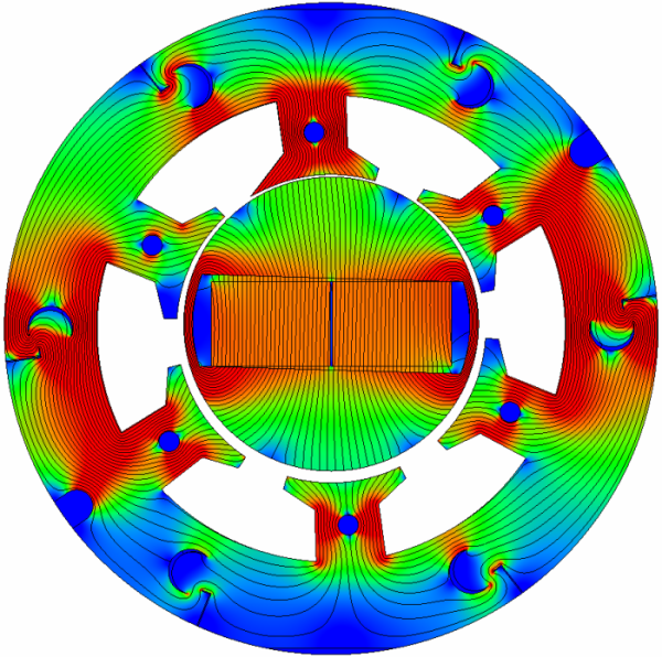 Fig. 2
Next, the joints 4 between the interlocked segments of the stator core cause marked distortions in the field. The gap around the dumb-bell interlock has been exaggerated, but the effect is clear, not only in the crescent-shaped gap around the dumb-bell but also around the narrow slit that forms on the outside of the core. The point is that even narrow gaps distort the field, and although the reduction in flux-density may be negligible, the distortion causes localized eddy-currents and increased core-loss.
The air-gap 3 between the stator and the rotor can be said to be the only legitimate and desirable gap in the entire machine, but here it is distorted by eccentricity. The result is that the rotor is closer to the top of the stator bore. It might stay there if the rotor axis is fixed in position (static eccentricity), or it might ‘whirl’ if the axis itself is off-centre (dynamic eccentricity). Although we cannot see it in the 2D diagram, the gap can also vary along the axial length if the rotor axis is inclined to the stator axis. These effects produce acoustic noise and torque undulations. Another effect is to disturb the balance between the N and S magnet fluxes, which can only be maintained by axially-directed residual flux which gets into the shaft and bearings, and causes eddy-currents in the transverse plane of the stator laminations and the rotor. Not nice. A full analysis requires 3D.
Then on the rotor we have a gap 2 between two magnet segments. The quality of modern magnet assemblies is nowadays so high that we would expect this to be rare. It can happen. But fortunately the effect is very small, as we can see in Fig. 2. Possibly a more serious imperfection is the clearance gap 1 which is here shown tapered. Again, the taper by itself is probably not too important because of the flux-gathering function of the surrounding steel; but the clearance gap is on average a deleterious feature because it reduces the effective strength of the magnet, probably by 1−3% in a typical case.
Finally the rotor in Fig. 1 has bridges at the edges of the magnet cavity, which are necessary to hold the rotor together. They are almost always present in the IPM, and the higher the speed, the thicker they must be. The problem with these is the shocking waste of precious magnet flux. Certainly the effect is much exaggerated in this example, but it is one of those mechanical constraints that stands between the real world and the ideal.
I know I wrote ‘finally’ in the last paragraph. But nothing is ever final in engineering. I forgot to mention the possibility that the magnetic properties of the core segments might be different. In Fig. 1 we can see two of these segments — the ones with the round-bottom notches — shaded in a slightly different colour. What can cause a difference in magnetic properties? Many things, including the rolling direction of the core plate, and the damage done during stamping and assembly.
Some of these imperfections may conceivably cause an error in the alignment of the magnetic field and the physical rotor, so it is theoretically possible that there would be a consequent degradation in performance if the controller cannot compensate. We are looking for minutiae, but minutiae have a habit of combining together into something bigger than the sum of the parts.
Last of all, sharp-eyed readers will have noticed that the uppermost stator tooth in Fig. 2 is mis-shapen. The left-hand tooth-tang is missing a vertex in the geometry of the associated region. JMAG has forgiven the dumb user, gone ahead, and solved the problem. But what if we were calculating cogging torque? What if we had a critical application where that error made the difference between ‘go’ and ‘no-go’? I don’t want to leave the reader with an unhappy thought. So I will point out that if we did have a motor with so many imperfections, including even the possibility of a ‘chipped tooth-tang’, at least we could calculate how much trouble we’d be in.
ご意見ご感想をお聞かせください。皆さま方からの貴重なお声として、今後の参考にさせていただきます。
なお、ご質問に関する回答は致しかねますので、あらかじめご了承ください。

