Overview
The centrifugal force generated when an IPM motor rotates at high speeds presses the magnets against the rotor core. The friction caused by magnet slip produces significant stress in parts. Stress that exceeds the yield point of a material results in plastic deformation that can lower motor performance or damage parts. That is why it is critical to accurately evaluate the impact of centrifugal force during the design stage.
This case study analyzes the magnet slip of an IPM motor by accounting for contact between the magnets and rotor core to obtain the displacement and stress distribution caused by the centrifugal force. The analysis clearly shows that the centrifugal force presses the magnets into the rotor core, which causes the magnet slip that concentrates stress in the bridge.
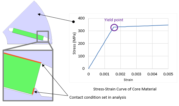
Fig. 1 Left: IPM Motor Model; Right: Stress-Strain Curve of Core Material
The IPM motor has four poles and 24 slots. The analysis models one-half pole of the rotor. Contact conditions are set to faces where the magnet and rotor core have contact to simulate the separation and slip between these parts. The yield point is 330 MPa as indicated by the stress-strain curve.
You need to sign in as a Regular JMAG Software User (paid user) or JMAG WEB MEMBER (free membership).
By registering as a JMAG WEB MEMBER, you can browse technical materials and other member-only contents for free.
If you are not registered, click the “Create an Account” button.
Create an Account Sign in