Overview
Recent miniaturization of various electric machines and power electronic devices demands smaller inductors. However, designs striving to sustain the same performance in a smaller structure tend to struggle with higher stray capacitance and lower self-resonant frequencies. The shift to higher switching frequencies in turn increases operating frequencies. Any operating frequency around a self-resonant frequency increases displacement current produced by the stray capacitance and causes losses. That is why inductor miniaturization has requirements contrary to those of higher operating frequencies.
JMAG offers magnetic field analyses that can account for displacement currents to evaluate wide-band designs that consider these fundamental trade-offs.
This case study examines the frequency characteristics of impedance in a chopper inductor with a laminated winding structure and one with a spiral winding structure. The results indicate resonance at 46 MHz in the laminated winding and 27 MHz in the spiral winding.
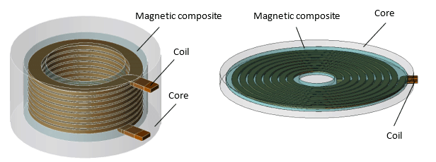
Fig. 1 Chopper Inductor
The analyses evaluate the frequency characteristics of impedance for
an inductor with a laminated winding (left) and an inductor with a spiral winding (right).
You need to sign in as a Regular JMAG Software User (paid user) or JMAG WEB MEMBER (free membership).
By registering as a JMAG WEB MEMBER, you can browse technical materials and other member-only contents for free.
If you are not registered, click the “Create an Account” button.
Create an Account Sign in