Overview

Magnetic field analysis simulation using the finite element (FEM) method is effective for accounting for differences in magnetic field strength due to three-dimensional positioning and interference from other magnetic parts.
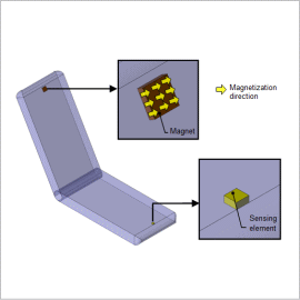
This Application Note presents how to obtain the magnetic flux density distribution at points in the horizontal and vertical directions away from the magnet.
Magnetic Flux Density Distribution
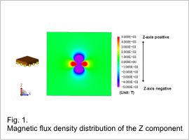
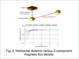
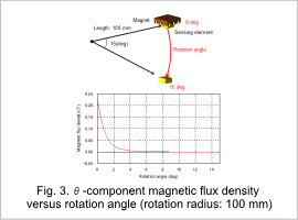
The magnetic flux density distribution of the Z component produced around the magnet is indicated in fig. 1. The horizontal distance versus Z-component magnetic flux is indicated in fig. 2. The rotation angle versus θ component magnetic flux is indicated in fig. 3. Positive values are indicated in the positive direction of the Z-axis, and negative values are indicated in the negative direction of the Z-axis. The magnetic flux density value at a spatial coordinate is analyzed ignoring the volume of the sensing element.
As indicated in fig. 1, the magnetization direction of the magnet has negative values on the Z-axis in the vertical direction, and works in the opposite direction in the horizontal direction. For this reason, if the sensing element is moved in a horizontal direction, the magnetic flux density that has a negative value in its initial position weakens toward a positive value when the sensing element is moved away from the magnet, as indicated in fig. 2. The direction of the magnetic flux density does not change within a rotation angle range of 15 deg, and the θ-component magnetic flux density decreases when the sensing element is moved away from the magnet, as indicated in fig. 3.
The magnetic flux density distribution can be evaluated in detail, and the detection range of the magnetic flux density can be estimated from these results.


