Customers currently in the duration of their trial period will not be able to download model data.
Please provide the application note numbers that you wish to review for your distributor support team.
Please be aware that services differ from the free-to-register “JMAG-Express Online” and the “JMAG Technical Library”.
Stepper motors are commonly used for positioning in printers and digital cameras. In PM stepper motors, the motor’s characteristics are determined through design of the magnetization state of the permanent magnet used. It is necessary to accurately evaluate this magnetization state in order to improve the precision of estimations of a PM stepper motor’s characteristics.
Detailed measurements of the magnetization distribution inside a magnet are difficult to make. However, it is possible to accurately find the magnet’s magnetization because it can be obtained through analysis of the magnetization field from the magnetization device, using the finite element method (FEM).
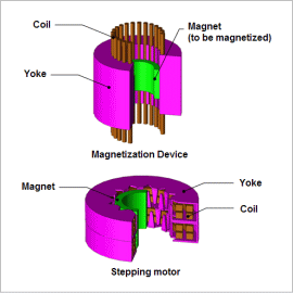
In this analysis, a magnetization device model is created and a magnet is magnetized. The magnetization distribution and surface magnetic flux density of the magnetized magnet, and the induced voltage of a PM stepper motor with the magnetized magnet integrated into it, are then obtained.
Magnetization Distribution and Surface Magnetic Flux Density of the Magnet
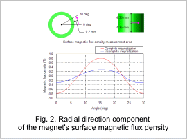
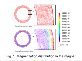
The magnetization distribution of the magnet magnetized by the magnetization device is shown in fig. 1, and fig. 2 shows the radial direction component of a two-pole span of the surface magnetic flux density at 0.2 mm from the magnet surface.
It can be seen from fig. 1 that magnetization is strong in all parts of the magnet under complete magnetization, and magnetization is weak toward the inner side of the magnet under incomplete magnetization. This is why in fig. 2, the maximum surface magnetic flux density value under complete magnetization is around 0.8 T, and is smaller at around 0.3 T under incomplete magnetization. This shows that it is necessary to consider the magnetization ratio and recoil relative permeability in order to grasp the magnetization state.
Induced Voltage Waveform
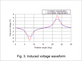
The induced voltage waveform of the stepper motor rotating at 1,000 r/min is shown in fig. 3. The figure makes it clear that the maximum induced voltage value goes down from around 7.5 V under complete magnetization to around 5.0 V under incomplete magnetization due to the difference in the strength of the magnet’s magnetization, and the PM stepper motor’s characteristics are different depending on whether the magnetization ratio and recoil relative permeability are accounted for or not.
This website uses cookies to improve functionality and performance. If you continue browsing the site, you are giving implied consent to the use of cookies on this website.
If you want to know more or refuse consent, read our Cookie Policy. Accept
Cookies Policy
Privacy Overview
This website uses cookies to improve your experience while you navigate through the website. Out of these cookies, the cookies that are categorized as necessary are stored on your browser as they are as essential for the working of basic functionalities of the website. We also use third-party cookies that help us analyze and understand how you use this website. These cookies will be stored in your browser only with your consent. You also have the option to opt-out of these cookies. But opting out of some of these cookies may have an effect on your browsing experience.
Necessary cookies are absolutely essential for the website to function properly. This category only includes cookies that ensures basic functionalities and security features of the website. These cookies do not store any personal information.