*Please prepare a license ID and password for the license administrator.
*It is different from the service for JMAG WEB MEMBER (free membership). Please be careful.
Overview
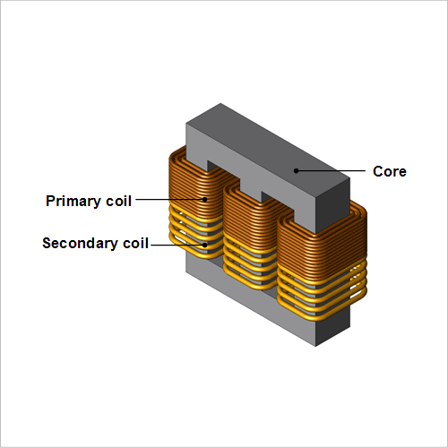
One of the most important principles in transformer design is how low loss can be kept to during operation. Iron loss in the transformer's core and copper loss in its coil become heat sources in addition to reducing efficiency, so they need to be understood and reduced from the standpoint of heat resistant design for all parts, particularly the coil's insulation.
An analysis using the finite element method (FEM) is effective in getting more information about thermal design by quantitatively evaluating the heat generation phenomena with copper and iron losses as heat sources, including the temperature distribution.
This Application Note presents an example of how to confirm a temperature distribution using the iron and copper losses of a three-phase transformer as heat sources.
Heat Generation/Temperature Distribution
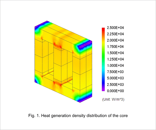
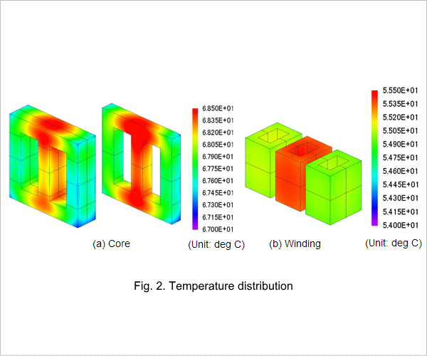
From fig. 1, it is apparent that the heat generation density is higher on the inside corners of the core. This is because the flow of magnet flux is concentrated in the shortest path through the magnetic circuit. The temperature around the bases of the core's center leg is higher because the heat generation density is higher there, as indicated in fig. 2(a). For this reason, the temperature of the winding at the center leg is also higher.