Overview
There are tradeoffs between dimensional tolerance, performance, and cost, so it is important to investigate these at the design stage. With numerical analysis using the finite element method (FEM), it is possible to evaluate the sensitivity of motor performance, such as torque, by simply changing the dimensions.
This Application Note presents how to assume a dimensional tolerance of ±0.4 mm for a chamfer, and find out whether changing dimensions within the tolerance range has an effect on motor performance by comparing cogging torque and induced voltage.
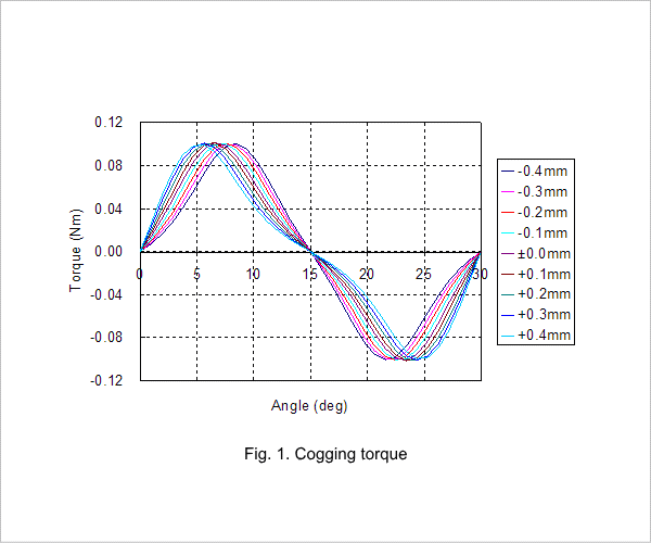
Cogging torque
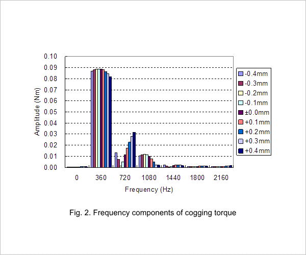
The cogging torque waveform is shown in fig. 1, and the frequency components of the cogging torque are shown in fig. 2. Although the location of the peak value is different when the size of the chamfer is changed, the peak value is almost the same, as indicated in fig. 1. Differences at the fundamental frequency of 360 Hz are small when compared with higher harmonic components, as confirmed by the frequency components in fig. 2.
From this, it can be determined that variations in the chamfer occurring within the tolerance range have little effect on the cogging torque.
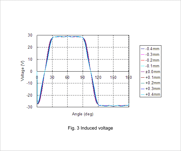
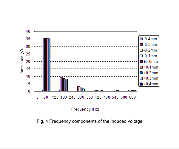
Induced voltage
The induced voltage waveform is shown in fig. 3, and the frequency components of the induced voltage are shown in fig. 4. Even when the size of the chamfer is changed, the induced voltage value is almost the same, as indicated in fig. 3. Differences at the fundamental frequency of 60 Hz are small when compared with higher harmonic components, as confirmed by the frequency components in fig. 4.
From this, it can be determined that there are few effects from the chamfer tolerance.