Overview
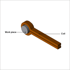
With induction hardening like the kind used on the work piece in this analysis, the main requirement is to heat a given surface uniformly and increase rigidity. The high-frequency’s varying magnetic field produces eddy currents with an offset in the surface of the work piece, so handling the phenomena inside the work piece with a numerical analysis based on the finite element method (FEM) is the most effective means analyzing the process in detail.
This Application Note explains how to create a numerical analysis model when obtaining the optimum coil geometry, current conditions (power supply frequency, current value), and rotation speed. It also shows how to evaluate whether the target temperature distribution is being achieved by analyzing the elevated temperature process.
Joule Loss Density Distribution
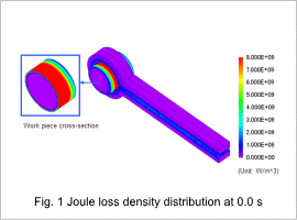
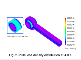
Figures 1 and 2 show the joule loss density distribution generated in the work piece and the coil. The magnetic field generated by the coil produces eddy currents in the work piece, which become heat sources in induction heating. The places where the heated part exceeds the Curie temperature lose their magnetism, so the eddy current loss density decreases, as well. The skin effect produced by the high frequency also causes the eddy current to be distributed near the work piece’s surface.
Temperature Distribution and Variation vs. Time
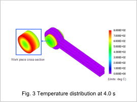
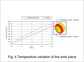
Fig. 3 shows the work piece’s temperature distribution, and fig. 4 shows its temperature variation versus time. In the surface facing the heating coil, the temperature is higher because more eddy currents are generated. As shown in fig. 4, induction heating causes the temperature in the surface of the work piece to rise first, and the temperature of the work piece’s interior rises gradually due to thermal conduction.
