*Please prepare a license ID and password for the license administrator.
*It is different from the service for JMAG WEB MEMBER (free membership). Please be careful.
Overview
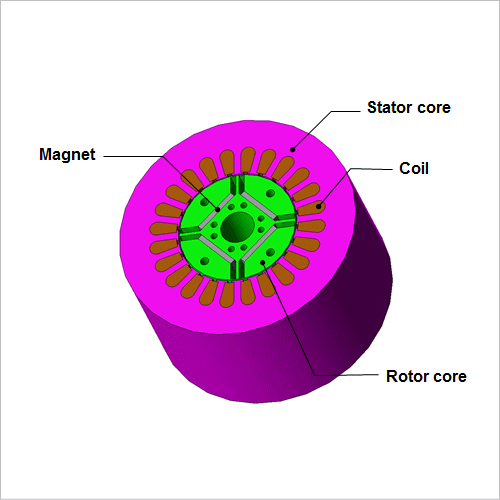
Demand for higher efficiency and smaller size in motors has grown from the need to accommodate devices that incorporate miniaturization and energy efficiency in their designs. In order to meet this demand, motors have to improve their output density and reduce their losses. One type of loss commonly found in motors is iron loss, which increases drastically at high rotation speeds and high magnetic flux densities. This increase can lead to a rise in temperature and a reduction in efficiency. Consequently, it is growing more important to predict iron loss at the motor design stage.
Unfortunately, it is not possible to obtain iron losses accurately in studies that use the magnetic circuit method or rules of thumb. In order to obtain them accurately, one needs to find the distribution and time variations of the magnetic flux density in each part of the motor after accounting for a fine geometry and the material's nonlinear magnetic properties. Using the finite element method (FEM) is essential in order to carry out this kind of a detailed analysis.
This Application Note demonstrates an analysis in which an IPM motor's cogging torque, torque, magnetic flux density distribution, and iron loss in the stator core are obtained.
Torque Analysis (No-load)
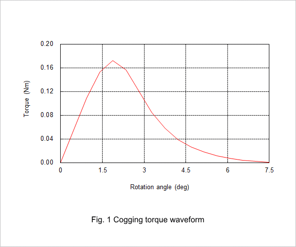
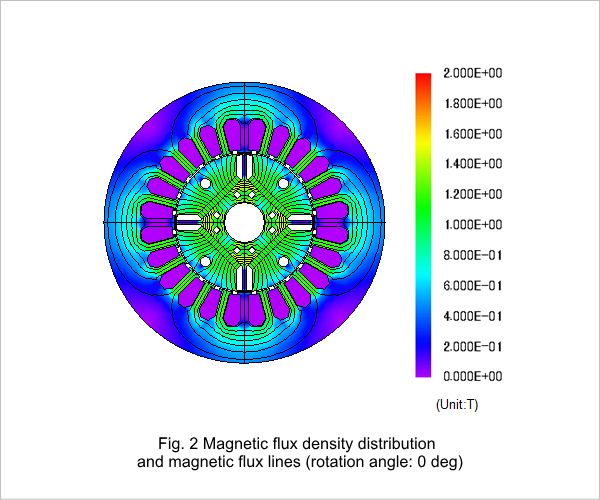
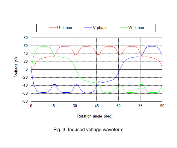
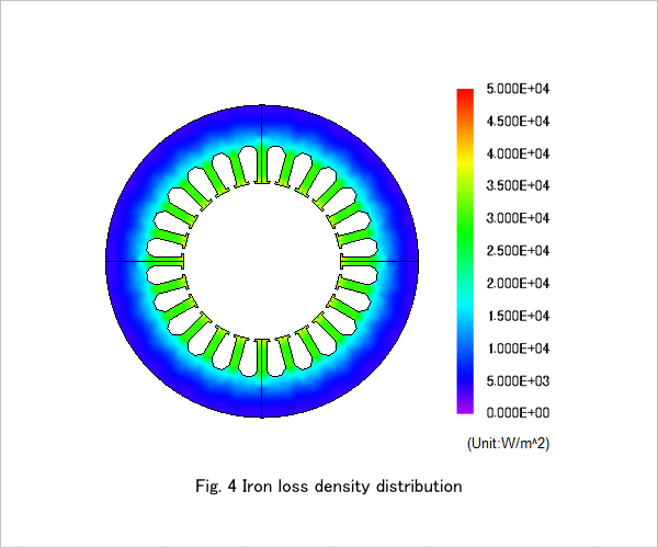
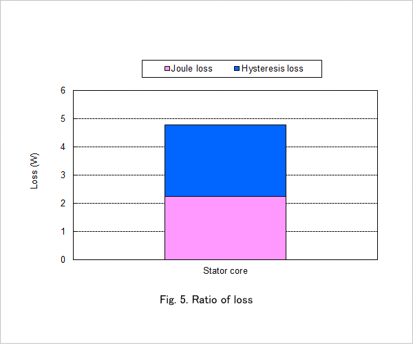
The cogging torque waveform is shown in fig. 1, the magnetic flux lines where the cogging torque is 0 Nm at a rotation angle of 0 deg are shown in fig. 2, the induced voltage waveform is shown in fig. 3, the iron loss density distribution is shown in fig. 4, and the losses are shown in Fig. 5.
Torque Analysis (Load)
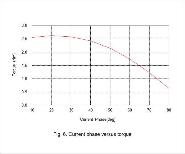
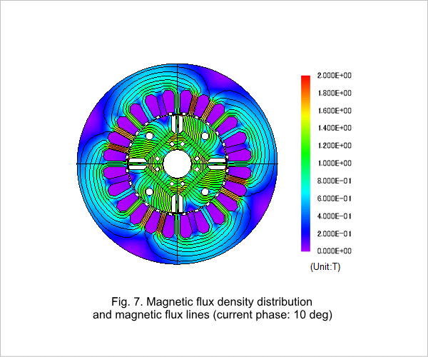
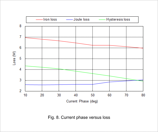
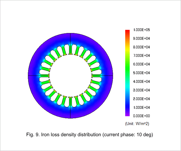
The current phase versus torque is shown in fig. 6, the magnetic flux density distribution and magnetic flux lines at current phase 10 deg are shown in fig. 7, the current phase versus loss is shown in fig. 8, and the iron loss density distribution at current phase 10 deg is shown in fig. 9.