Overview

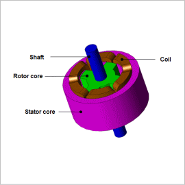
SR motors operate using the nonlinear region of a magnetic steel sheet, so because the inductance displays nonlinear behavior, it is impossible to carry out advanced projections that are accurate with calculation methods that follow linear formulas. Consequently, it becomes necessary to use the finite element method (FEM), which can handle nonlinear magnetic properties in material and minute geometry.
This example presents an evaluation for each rotor position of the effect on flux linkage (shown as I-Psi characteristics below) when excitation current is changed.
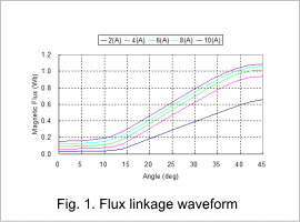
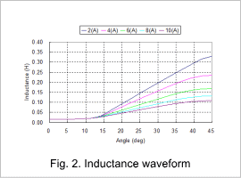
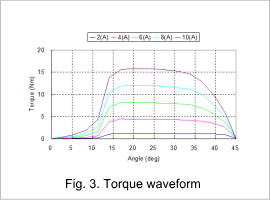
Flux linkage waveform / Inductance waveform / Torque waveform
For each rotor’s position change, the SR motor’s flux linage waveform is indicated in fig. 1, the inductance waveform in fig. 2, and the torque waveform in fig. 3.
From fig. 1 we understand that in the range of 45 deg when the tooth is facing to each other, the more the current is increased, the more the amount of magnetic flux decreases. As a result, as the currency value increases, inductance decreases, which we also understand from fig. 2. These are due to the nonlinear properties of the core material.
In fig. 3 it is possible to estimate the approximate average torque for each current value. Also, it is possible to consider geometry in accordance with setting specifications, such as peaks and reductions in the torque.


