*Please prepare a license ID and password for the license administrator.
*It is different from the service for JMAG WEB MEMBER (free membership). Please be careful.
Overview
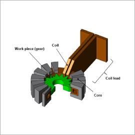
Gears are created in such a way that the surfaces of their teeth are hard in order to resist the wear and tear that occurs when they come into contact with the teeth of other gears. However, this has to be accomplished while maintaining the gear’s overall toughness. By using high-frequency induction heating, which is a type of surface hardening method, the teeth are heated rapidly on only their surface by a high frequency power source. This process also has many other benefits, such as providing a clean working environment because it uses electrical equipment, being very efficient, and providing uniform results for each product. This is why it is being aggressively implemented in the field. On the other hand, there are several factors that need to be studied in order to heat the gear’s surface uniformly, such as how to adjust the heating coil’s geometry, arrangement, current frequency and size.
The eddy currents generated by high-frequency varying magnetic fields are uneven in the tooth surface, so the material properties change a great deal as the temperature rises. In order to handle the detailed phenomena, it is necessary to calculate the heat generation amount in a numerical analysis based on the finite element method (FEM).
In this material, the validity of coil geometry used for quenching is evaluated by heating the gear top and bottom at high and low frequencies, respectively, to confirm uniform temperature distribution on the surface of the gear.
Eddy Current Loss Density Distribution of the Work Piece
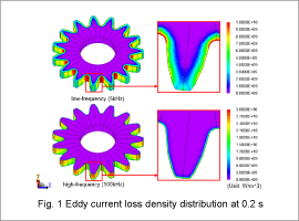
Fig. 1 shows the eddy current loss density distribution of the surface of the work piece and the cross-section of a tooth top. Eddy current loss density distribution is shown in both low and high frequencies. Each cross-section shown in the figure at the midway position of the tooth width. The magnetic field generated by the coil produces eddy currents on the work piece surface. This eddy currents are distributed on the surface of the work piece due to the skin effect.
It’s also possible to confirm the changes in the eddy currents due to different frequencies. Eddy currents are distributed on the work piece bottom at low frequency and on the work piece surface and tip at high frequency due to the skin effect.
It’s also possible to confirm the changes in the eddy currents due to different frequencies. Eddy currents are distributed on the work piece bottom at low frequency and on the work piece surface and tip at high frequency due to the skin effect.
Temperature Distribution and Variation of the Work Piece
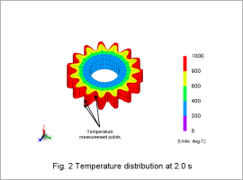
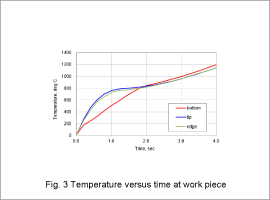
Temperature distribution in the work piece is shown in Fig. 2. Fig. 3 shows the time characteristics of temperature variations at each temperature measurement point. From the temperature distribution, it is apparent that the eddy currents generate heat in the tooth top.
The difference in heat generation from the coil geometry can also be verified in Fig. 3. It is also possible to confirm at each measurement point that the temperature exceeds the Curie point of 800 deg C at around 2.0 sec.
Magnetic Flux Lines
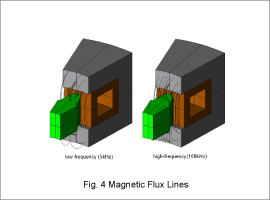
The Magnetic flux lines are shown in fig. 4. It can be confirmed that magnetic flux is flowing from the core to the top of the work piece.


