*Please prepare a license ID and password for the license administrator.
*It is different from the service for JMAG WEB MEMBER (free membership). Please be careful.
Overview
![[JAC206] Temperature Analysis of an Oil-Immersed Transformer Using a Coupled Magnetic Field and Thermal Fluid Analysis](/images/catalog/e206-0.gif)
Large power transformers are used to transform high voltage power generated at a power station into power that can be transmitted. For the structure of the transformer, oil-immersed transformers, which fill the inside of the tank that contains the transformer body with insulating oil for cooling and insulation, are often used.. The insulating oil for the oil-immersed transformer is sometimes forced to circulate using a pump, and sometimes made to flow naturally.
In order to estimate the temperature of the winding and core of the oil-immersed transformer, heat transfer from the insulating oil must be estimated. Various structures exist inside the tank besides the core of the transformer and winding, such as clamps for supporting cores and shields for preventing magnetic field leakage. Whether circulation is forced or natural, the flow channel is complex, and estimating heat transfer is not an easy task. Especially in areas where structures block flow channels and other areas with large amounts of localized heat generation, hotspots with high temperatures may be formed. In order to understand and accommodate for these phenomena, a loss distribution analysis, as well as a thermal fluid analysis accounting for the flow path of the insulating oil are necessary.
This document introduces, examples and steps will be shown to obtain heat distribution in a magnetic field analysis for a forced circulation type oil-immersed transformer, map the thermal distribution to thermal fluid analysis model, and then obtain the temperature by handling the insulating oil as a fluid in a thermal fluid analysis.
Loss
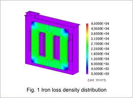
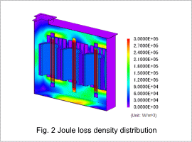
Iron loss density distribution occurring in the core of the transformer obtained in the magnetic field analysis is shown in fig. 1, and distribution of copper loss and stray load loss (joule loss density distribution) occurring outside the core are shown in fig. 2. The main components for the loss amounts are iron loss in the core and copper loss in the winding, but when looking at the loss density, it shows that losses are also high in the connector.


Flow Rate Distribution (Streamline)

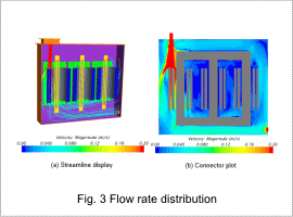
Flow rate (streamline, contour) of the insulating oil obtained in the thermal fluid analysis is shown in fig. 3. When looking at the streamline, the insulating oil flowing in from the entrance keeps moving downward, and flow rate in the U-phase winding is larger. On the other hand, we can see that flow rate is smaller in the W-phase winding side compared with the U-phase winding side. Furthermore, because the flow passage for the V-phase in the center is narrow, insulating oil cannot easily enter, and the flow rate is also very small.
Temperature

Flow rate (streamline, contour) of the insulating oil obtained in the thermal fluid analysis is shown in fig. 3. When looking at the streamline, the insulating oil flowing in from the entrance keeps moving downward, and flow rate in the U-phase winding is larger. On the other hand, we can see that flow rate is smaller in the W-phase winding side compared with the U-phase winding side. Furthermore, because the flow passage for the V-phase in the center is narrow, insulating oil cannot easily enter, and the flow rate is also very small.


