*Please prepare a license ID and password for the license administrator.
*It is different from the service for JMAG WEB MEMBER (free membership). Please be careful.
Overview
The square wires and flat wires of segment coils and edgewise coils, etc., are being used for the purpose of improving lamination factors, the reduction of end parts, minimization, improvements in heat dissipation, and improvements in productivity in IPM motors. On the other hand, from the viewpoint of higher efficiency and increasing output, etc., motor coil resistance to loss is becoming a necessity as so to obtain a reduction of loss in electrical appliances in general.
When increasing the number of motor rotations, concentration of electric current occurs within the coil interior due to the eddy and current joule loss value increases. Especially at high rotation such as 10,000 r/min, joule loss may increase from 3 times to 4 times compared with low speed. In running accurate evaluations of joule loss and handling concentration of electric current within the wire correctly, it is also important to properly manage the eddy current generated by the distribution of magnetic flux density that links the wire and temporal changes to magnetic flux density. For these reasons, simulation via magnetic field analysis is a necessity.
In this example, evaluation of coil joule loss that includes eddy currents during motor rotation is introduced here.
Comparison of Winding Joule loss
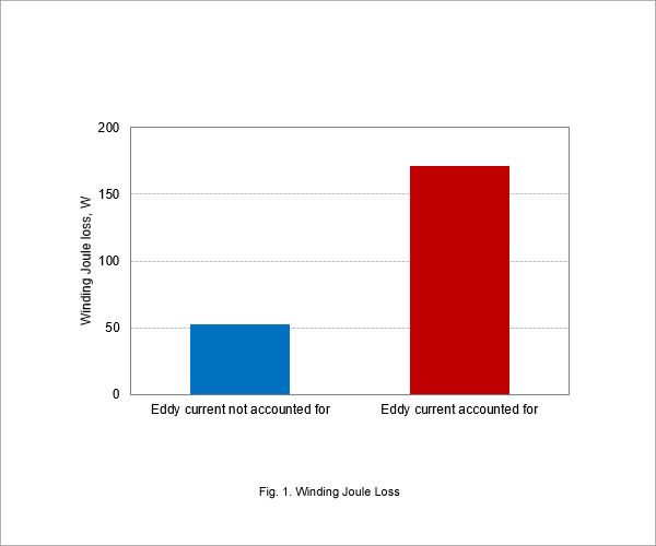
Coil joule loss when using fundamental frequency and PWM waveforms as input at 10,000 r/min is displayed in Fig. 1. It is understood that joule loss increases over 3 times more when the eddy current is accounted for, compared to when the eddy current is not accounted for.
Joule Loss Density Distribution When Accounting for Eddy Current
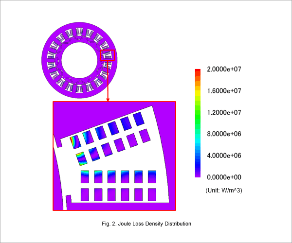
Wire joule loss density distribution (at a time of maximum U phase current) when the eddy current is accounted for is displayed in Fig. 2. It can be seen that gap side wire loss density is high and offset is large. From this it is understood that there is considerable eddy current generation at this position.
Flux Linkage per Component
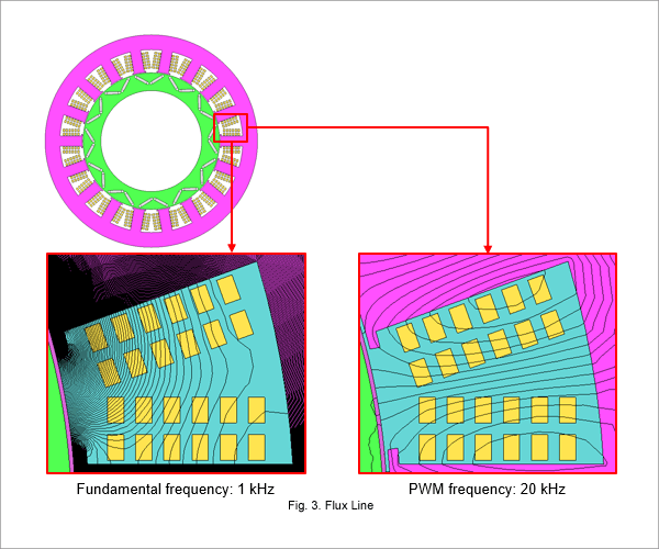
Magnetic flux lines when eddy current is not taken into account are investigated and the relationship between magnetic flux linking the strand and its Joule loss is confirmed. Fig. 3 shows the flux lines.
In Fig. 3, Observing the fundamental wave component shows that the leakage flux from the rotor is concentrated in the wires near the air gap and links with them. Observing the PWM frequency component shows that the magnetic flux links with the entire wire. From this results, joule loss concentration within wires near the gap is thought to be caused by the link with fundamental frequency flux components.
In Fig. 3, Observing the fundamental wave component shows that the leakage flux from the rotor is concentrated in the wires near the air gap and links with them. Observing the PWM frequency component shows that the magnetic flux links with the entire wire. From this results, joule loss concentration within wires near the gap is thought to be caused by the link with fundamental frequency flux components.

