*Please prepare a license ID and password for the license administrator.
*It is different from the service for JMAG WEB MEMBER (free membership). Please be careful.
Overview

Electric Machines are affected primarily by 3 types of losses. Iron losses in steel lamination sheets, joule losses in the conducting components and joule losses in coils.
When we primarily focus on AC losses in coils, one way to reduce them is by using a “Bar winding”. Bar winding is used large conductor bars, so this improves fill factor and reduces DC resistance which in turn reduce DC losses. Large cross section of these windings cause make them vulnerable to AC losses like skin effect and proximity losses. The AC losses are frequency dependent so if the machine operates on higher frequencies and higher speeds.
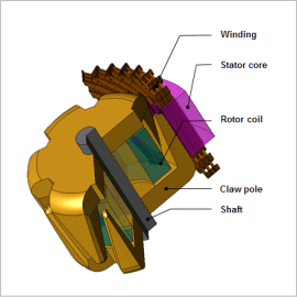
In order to examine the AC losses we use a bar wound claw pole alternator which is a three dimensional machine. This allows us to examine the AC losses in greater depth and get their full impact. These losses cannot be calculated via the equivalent circuit method. Hence finite element method has to be used.
In this example, we introduce the case study that evaluates AC losses in coils of claw pole alternator.
Loss Analysis
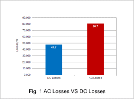
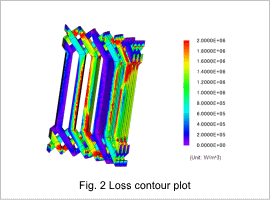
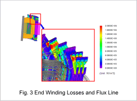
Fig. 1 shows AC losses vs DC losses. Fig. 2 shows loss distribution of coils. Fig. 3 shows loss distribution and flux line of end windings.
From fig. 1, we can observe that the effect of AC losses is significant on the overall efficiency, thus they cannot be ignored.
In fig. 2, most of the losses are concentrated on the edges of the coil geometry than the insides. This is one of the characteristics of AC Losses.
From fig. 3, we can confirm the relationship of loss distribution and magnetic flux in the end windings.


