Overview
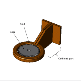
On the other hand, in order to uniformly heat the surfaces of the gear, it is necessary to consider several factors such as how to adjust the geometry, arrangement, frequency, and size of the heating coil.
Eddy currents generated by high-frequency varying magnetic fields are generated near the surface of the teeth. As temperature rises material characteristics change drastically, and the object heated is thermally deformed by thermal stress. It is necessary to compute heat generation amounts and deformation amounts in numerical analysis using finite element methods (FEMs).
In this example, using the JMAG magnetic field – thermal stress coupled analysis function, analysis is performed evaluating gear deformation from induction heat hardening.
Eddy current Loss
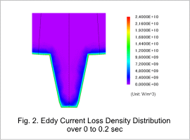
A high-frequency (30 kHz) current flows in the coil causing a magnetic field fluctuation which induces induced current in the gear. Due to the skin effect, current concentrates on the tooth tips of the gear.
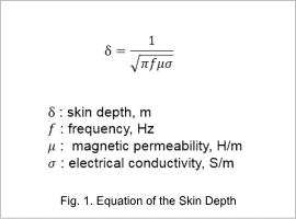
Skin thickness can be calculated by the equation shown in Fig. 1.
From magnetic field analysis, induced current in the model can be checked. The loss due to the induced current is used as a heat source for thermal stress analysis. The temperature distribution in and on the gear and deformation of the gear obtained from thermal stress analysis are input as conditions in magnetic field analysis.
Fig. 2 shows the eddy current loss density distribution on a cut surface of a gear tooth tip.
Temperature Distribution
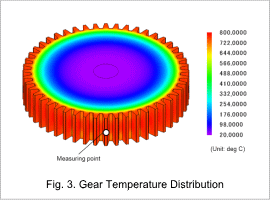
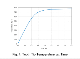
Loss due to induced current acts as a heat source increasing temperature. In thermal stress analysis, the loss obtained from magnetic field analysis is set as an input condition. Since losses concentrate primarily on the tooth tips which are outside the model, this region naturally becomes the region of maximum temperature change. Material magnetization characteristics and temperature characteristics of electrical characteristics are taken into account using an obtained temperature distribution as an input condition for magnetic field analysis.
Fig. 3 shows the temperature distribution on the gear, and Fig. 4 shows the temperature vs. time of a tooth tip. Fig. 4 shows the change in temperature at the tooth width center shown in Fig. 3.
Thermal Stress (Deformation)
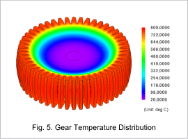
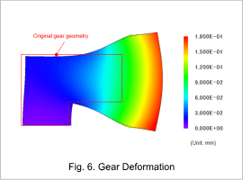
The deformation of and temperature distribution on the gear at a 4 sec are shown in Fig. 5, and the deformation of the gear is shown in Fig. 6. The thermal expansion deformation of the model is confirmed at 100 times magnification.
As the gear temperature changes, deformation occurs due to thermal expansion and thermal contraction. During this time, thermal stress is produced due to for example constraints and an uneven temperature distribution. From the figure, it can be seen that the areas of highest temperature expand the most. After heating for 4 sec, the tips are deformed to a maximum of 0.18 mm. Furthermore, the gear is drawn toward the ground by gravity. The influence of gravity on the deformation can also be confirmed.
